
Manufacturing and Quality at EverBen
We bring transformer manufacturing and cabinet fabrication together around your power requirements. Our work covers transformers, voltage stabilizers, AC power supplies, electrical cabinets and electric meter boxes, with electrical performance and practical installation considered together.
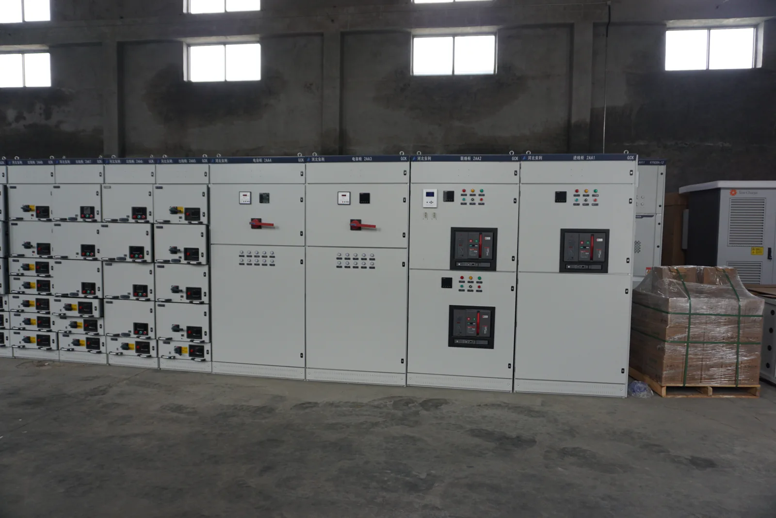
Our annual production capacity is 20,000 transformers and 3,000 voltage stabilizers. Our experienced engineers and technicians support product design, sample development, material selection, manufacturing and final inspection, including configurations tailored to customer requirements.
We turn application requirements into equipment configurations
We begin with the supply and the load: input and output voltage, phase, frequency, capacity, starting demand and operating duty. These inputs shape winding arrangements, terminals, cooling and the space needed around the equipment.
We also discuss the installation environment, cable approach and access with your team. A transformer for an export machine and a fitted distribution cabinet have different interfaces, even when they serve the same project. Our product families provide the starting point for connecting those requirements to a workable configuration.
Our drawings connect design, fabrication and assembly
We use the electrical and mechanical layout to bring the project together. The general arrangement defines the equipment envelope, mounting points, cable entries and access; the electrical diagram and component schedule define the connections and devices inside.
We coordinate these details with your equipment or site team before the configuration moves into production. Clear drawing revisions keep a changed terminal position, enclosure dimension or component choice connected to the relevant assembly. This gives both teams a common reference for manufacturing and installation preparation.
We select materials around electrical and mechanical duty
Material selection connects the electrical design with the manufacturing process. We consider conductor and terminal compatibility, magnetic performance, insulation processing and enclosure exposure together, then define the selected construction for the project.
| Design area | Performance and processing factors | What we coordinate |
|---|---|---|
| Winding conductor | Electrical resistance, winding space and connection geometry | Material, section and termination design |
| Magnetic core | Magnetic circuit, losses and resulting heat | Core construction with voltage, frequency and duty |
| Insulation | Electrical separation, thermal conditions and impregnation | Materials and processing suited to the winding design |
| Cabinet panels | Rigidity, formed features and environmental exposure | Base material, thickness, finish and mounting |
| Fitted components | Device ratings, connections and service space | Part selection, terminal layout and assembly dimensions |
We agree these choices as a coordinated design so a material or component change can be considered alongside its electrical and mechanical effects.
Our winding and insulation processes build the transformer
Foil and wire winding
Our production equipment includes large foil-winding machines and wire-winding machines. We match the winding approach to the transformer design, arranging the conductor, insulation and lead exits around the required coil geometry. Winding dimensions also affect how the coil fits the core and how its terminals connect to the surrounding equipment.
VPI and thermal processing
Our vacuum-pressure impregnation equipment and high-temperature ovens support winding insulation processing. Impregnation carries insulating material into the winding; oven curing develops the material's protective and bonding properties. We select the process conditions for the insulation system and construction. The processed winding then forms part of the core-and-coil assembly, with its supports and connections coordinated for the finished transformer.
Our isolation transformer configurations connect these winding and insulation choices to the required source-to-load separation.
We fabricate cabinets around the equipment inside
Cutting and forming
We translate enclosure drawings into cut panels and formed parts. Openings, folds and fixing positions connect the external cabinet dimensions to the mounting space inside. Door geometry and access are considered alongside the panel structure.
Component installation and assembly
Our cabinet work brings the enclosure, mounting hardware, devices and terminals together. We coordinate cable routes, component spacing and access for operation and maintenance. For a fitted assembly, the layout and connection schedule connect the physical build to its electrical function.
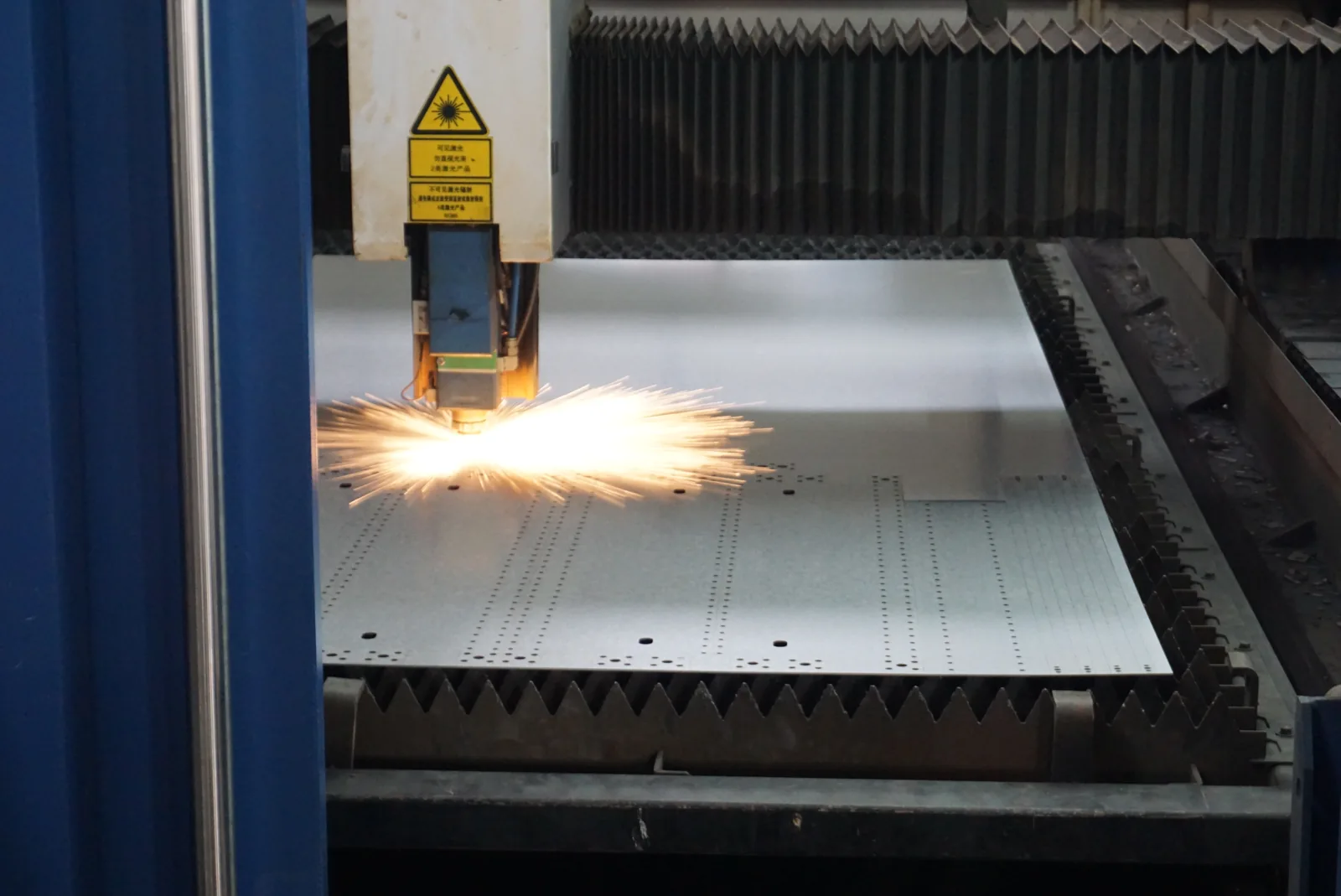
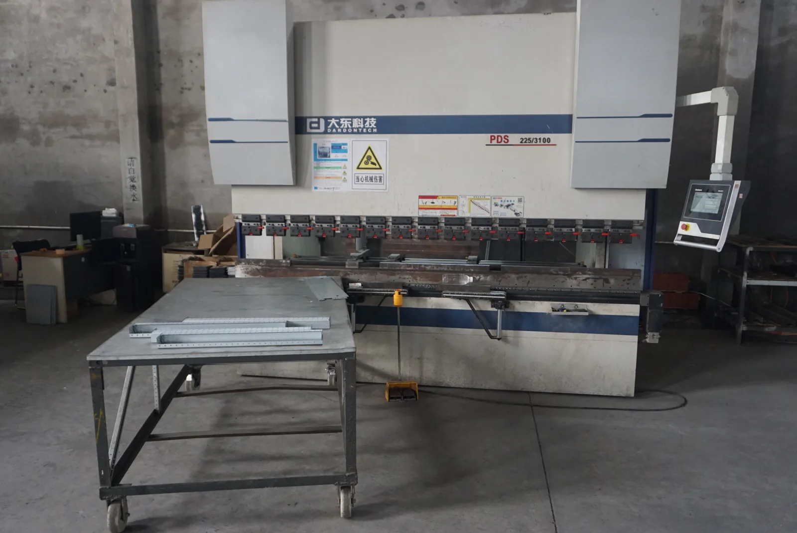
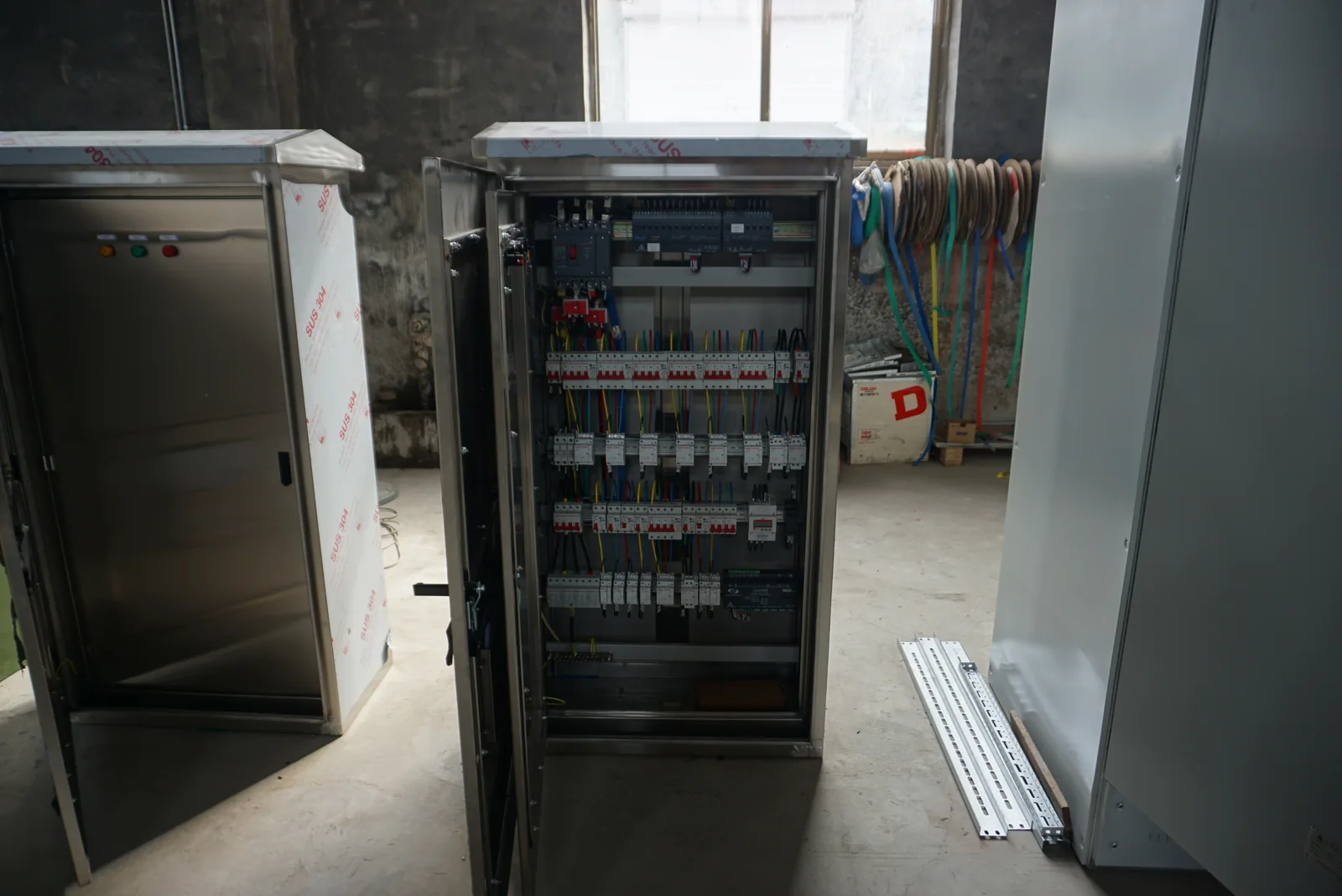
Our electrical enclosure configurations bring material, door, mounting and cable-entry choices into the fabrication layout.
Our quality checks follow the equipment configuration
We connect the inspection plan to what the equipment must do. The relevant checks cover its dimensions and assembly, electrical characteristics and, where fitted, control functions. We agree the methods, conditions and acceptance criteria with the project requirements.
| Check area | Project focus |
|---|---|
| Dimensions and assembly | Envelope, fixings, openings, component arrangement and access |
| Electrical characteristics | Winding, insulation, supply and load characteristics relevant to the equipment |
| Control functions | Connections, indications and specified operating sequences |
| Project-specific checks | Additional conditions, customer attendance and required results |
We coordinate production checks and project testing
Routine checks and design verification
Routine checks address the manufactured unit. Type testing or design verification addresses the performance of a defined design or construction. We keep these purposes distinct when discussing the appropriate test scope for a transformer, power supply or fitted cabinet.
Customer witnessing and additional conditions
Where witnessing or additional testing forms part of the order, we agree the equipment configuration, conditions, acceptance criteria and attendance arrangements together. This connects a customer's inspection requirements to the production plan and keeps the resulting documents relevant to the supplied equipment.
Our test equipment supports electrical and thermal assessment
Our testing equipment includes core-loss and interturn-withstand instruments, a high-current comprehensive load platform, high-power variable-frequency AC test supplies and temperature-monitoring equipment. Each serves a different part of the electrical or thermal assessment.
| Equipment | Assessment focus |
|---|---|
| Core-loss instrument | Loss characteristics of the magnetic core |
| Interturn-withstand instrument | Insulation between winding turns |
| High-current load platform | Behavior under the specified load conditions |
| Variable-frequency AC test supply | The electrical supply conditions used during testing |
| Temperature monitoring | Temperature behavior during the defined test |
We align the selected checks with the equipment's duty and project requirements. Test conditions, measured results and equipment identification give the agreed report its practical meaning.
Our AC power supplies support discussions about the voltage, frequency and current conditions needed at each test operating point.
How we organize an acceptance record
We organize the agreed inspection record around the selected equipment, approved drawings and acceptance criteria. These fields connect each result to its test conditions and order reference.
| Record field | Information to enter for the order |
|---|---|
| Equipment identification | Model, serial number and order reference |
| Configuration reference | Drawing number and approved revision |
| Check item | Applicable dimension, connection or electrical characteristic |
| Conditions and method | Test setup, supply, load, duration and ambient conditions as applicable |
| Agreed acceptance criterion | Order requirement or referenced drawing limit |
| Measured or observed result | Result and units, or observation |
| Acceptance decision | Comparison with the agreed criterion and any corrective action |
| Record identification | Date, record reference and responsible person |
A dimension check can refer to the approved outline drawing; a connection check can refer to the terminal schedule. For an applicable electrical test, we connect the result to the recorded conditions and agreed criterion. This makes the handover record useful to engineering, quality and receiving teams.
We coordinate changes across the complete configuration
A different component, cable entry or winding requirement can affect more than one drawing. We discuss the electrical, dimensional and production implications with your team so the agreed change remains consistent across the equipment.
Our project coordination links the revised configuration to the affected component list, labels and checks. Where an inspection identifies an issue, the next step is to define the correction and any repeat check needed before the agreed release. This keeps configuration decisions connected to the finished build.
Clear identification connects the product to its application
We coordinate equipment identification, declared ratings and terminal labels with the final configuration. Model and serial references help connect the physical unit to its drawings, operating information and later support discussions.
For a cabinet assembly, clear device and circuit identification also helps the installation team relate the internal layout to the connection schedule. We discuss destination marking and document requirements during configuration so they can be included in the order.
We prepare the equipment for transport and receipt
We discuss the transport route, handling arrangements and site access when preparing the delivery scope. Equipment dimensions describe the installed unit; package dimensions and gross weight support transport and unloading planning.
Our packing coordination considers protection for finishes, doors, terminals and supplied accessories. Package identification and the packing list connect the shipment to the ordered equipment. We agree the drawings, inspection information and operating documents to accompany the project, giving the receiving team a clear basis for identifying the delivery and preparing installation.
We keep follow-up discussions tied to the supplied equipment
Our technical team can address product and configuration questions using the model, serial number, drawing reference and relevant component details. These references help us distinguish an original part, a revised configuration and a new application requirement.
For replacement-part discussions, we consider the mating features, electrical role and installed arrangement together. Clear photographs of accessible identification and the relevant drawing make the conversation more precise. We define the requested parts, documents and support scope in the project agreement so your team can coordinate the next step.
Discuss your manufacturing requirements with us
Tell us about your equipment family, supply and load, quantity, destination and installation conditions. We can then discuss the configuration, manufacturing requirements and project documents together. Include special inspection or witnessing needs early so they can be considered with the production scope.
Whether your project begins with a transformer, stabilizer, AC power supply, cabinet or meter box, we welcome a conversation about the complete equipment requirement.
Email: power@chinatransformermanufacturer.com. Contact our team.