
Surface-Mounted Meter Boxes
We configure surface-mounted meter boxes around the space available on a wall or support. Our layout brings the meter interface, enclosure projection, fixing points and cable approach together for practical reading and service access.
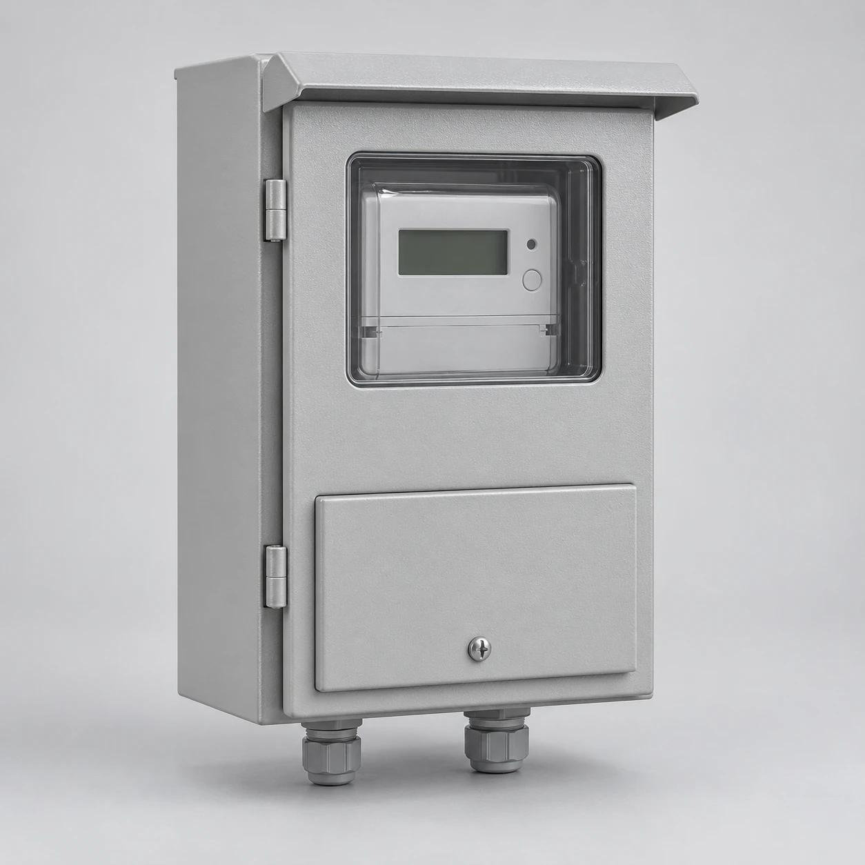
We consider the enclosure and its selected contents together, so the mounting arrangement reflects the finished dimensions and assembled weight. Brackets, accessories and fitted devices are identified in the project scope.
Our surface layouts work with the available wall space
A surface-mounted enclosure sits on the face of its support, keeping its depth outside the wall. We consider that projection alongside the wall footprint, nearby equipment and the normal approach to the meter.
A recessed meter box instead connects to an opening within the surrounding construction. We discuss these building interfaces with your team before developing the detailed electrical layout. For an existing installation, the intended change may be a replacement in the same position, a larger box or a move to another support; each has a different geometry to coordinate.
We align the enclosure with the meter and service
We coordinate the service voltage, frequency, conductors and selected meter or socket with the equipment assigned to the enclosure. Our single-phase and three-phase meter boxes content explains the related service arrangements.
The mounting board, meter interface, terminals and any main equipment each need space inside the housing. We identify which components are included in the project and which are provided by the utility or other parties. That component arrangement also establishes the populated weight and influences the mounting design.
We coordinate footprint, projection and opening space
Front footprint and fixings
We distinguish overall width and height from the fixing-hole centres. A defined datum and clear units, such as mm or inches, let the enclosure drawing and the site dimensions refer to the same points.
Side projection and door movement
Depth from the support face affects the space occupied in a walkway or equipment area. We also consider the open door and removable covers, keeping their movement separate from the internal space needed by the meter. The front and side views help bring these relationships into one discussion.
Weight and fixing data connect the box to its support
We distinguish the empty enclosure from the populated assembly so the mounting information describes the equipment that will actually be installed. Metering devices, terminals and other fitted parts contribute to the finished mass.
| Information | Project purpose |
|---|---|
| Empty-enclosure weight | Identifying the housing configuration |
| Assembled weight | Coordinating the support with the fitted equipment |
| Fixing and bracket dimensions | Matching the enclosure to the support interface |
| Packed weight and dimensions | Planning transport, unloading and receipt |
We keep the units and configuration reference with these values. The site's installer or structural designer selects anchorage for the actual substrate and load, using the equipment mounting information.
Our entry layout connects the cables to the terminals
We consider the proposed top, bottom or rear cable approach alongside the meter and terminal positions. Entry coordinates, fitting dimensions and conductor bend space determine how the installation route meets the box.
We coordinate permitted openings and the selected hubs or glands with the enclosure construction. This also helps preserve the intended sealing arrangement around each cable interface. The result is a layout in which the cable can reach its terminal without competing with the meter, mounting supports or normal cover access. Entry changes are handled together with the affected drawing details.
We keep the meter and door accessible in the installed position
The display position, viewing window where selected, hinge side and latch location all influence everyday use. We consider these details against the wall, surrounding pipes, fences and adjacent cabinets so a fitting footprint also has workable access.
Door swing and removable-cover clearance are shown as part of the installation arrangement. We coordinate the customer-accessible area and utility sealing zones with the selected meter layout. Authorized meter work and internal electrical service remain with the appropriate utility parties and qualified personnel, while normal reading uses the intended display access.
We choose construction around exposure and mechanical duty
Body and surface protection
Metal construction offers rigidity for panels, doors and mounted equipment, with the finish selected around corrosion and exposure. Non-metallic construction offers an insulating structure and can reduce weight; sunlight, impact and temperature remain part of its material selection.
Doors, seals and entries
We consider the door, viewing window, gasket and cable fittings as a connected enclosure system. Their interfaces influence closure and environmental performance. Our outdoor meter boxes content develops external exposure choices. Surface mounting describes the installation format; the selected construction addresses the environment.
We compare new and existing mounting interfaces
For a new installation, we align the support, cable approach and metering layout before the enclosure dimensions are settled. That gives the site team a common basis for preparing the mounting area.
For a replacement or retrofit, we compare the existing and proposed footprint, fixing points, projection, cable entries and door area. Accessible identification, exterior photographs and available drawings provide the starting information. Any concealed measurements are handled through the team's authorized survey. We discuss resulting changes to the enclosure interface with your team so building work and service coordination can follow the selected arrangement.
We connect packing, accessories and replacement references
We discuss packing with attention to projecting parts, door edges, mounting provisions and any supplied brackets. Clear package and accessory identification help the receiving team relate the delivered pieces to the equipment layout.
For later questions, the enclosure reference and mounting drawing help us identify the relevant door, hinge, gasket or support interface. Our meter-box doors and accessories page explains the matching details. A change in one part can affect closure or alignment, so we consider the mating features together when discussing replacement requirements.
Discuss your surface-mounted meter box with us
Start with the support surface, available wall space, allowed projection and meter reference. Add the cable approach, installation location and quantity if known. We can then discuss the enclosure layout and the selected components with your team.
For a retrofit, mention the existing model and the exterior drawings or photographs available for follow-up. The mounting and meter details help us focus the conversation on fit, access and the connections that matter to your project.