
Transformer Integration for Industrial Machinery
We match industrial machinery to the available site supply. Our transformer configurations connect the machine's voltage and load requirements with the winding arrangement, control power and installation layout, helping your equipment and electrical teams work from the same power-interface plan.
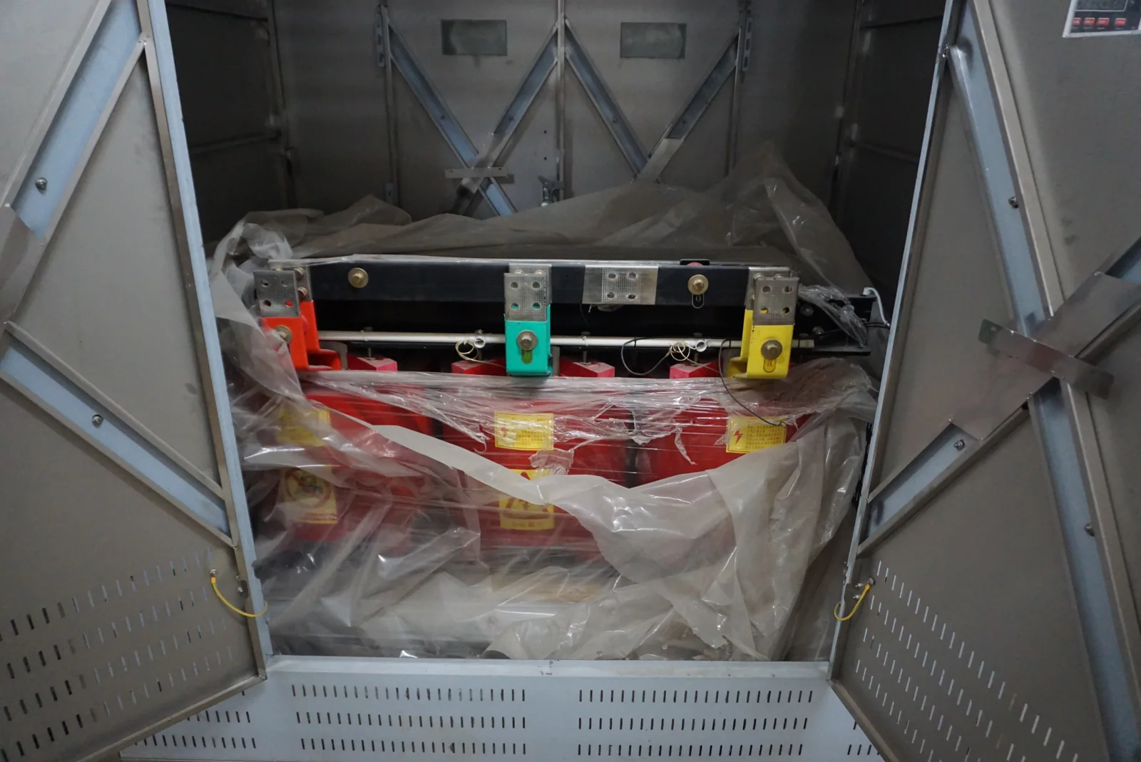
Machine power that fits the installation
Imported equipment, production-line additions and machine relocations can bring a voltage requirement that differs from the available supply. We work with voltage-matching requirements such as 480 V to 380 V, 600 V to 380 V and 440 V to 380 V, starting with the actual machine and site values.
The voltage pair is connected to the phase arrangement, operating range and load. Line-to-line and line-to-neutral references matter, as do separate requirements for motors, heaters and controls. By considering the whole machine input, we can discuss the transformer in its operating context rather than treating its nominal voltage as the entire application.
Choose the function that resolves the supply difference
A transformer changes voltage while retaining the incoming AC frequency. That makes it useful for voltage matching when the machine accepts the site frequency. A frequency mismatch or a varying supply calls for a different function, sometimes alongside a transformer.
| Machine requirement | Power function | Configuration focus |
|---|---|---|
| Different voltage | Transformer | Ratio, load and winding arrangement |
| Different frequency | AC frequency source | Complete machine input and output operating points |
| Variable incoming voltage | Voltage stabilization | Input variation and permitted output band |
| Separate auxiliary circuit | Control-power configuration | AC/DC requirements and device operating sequence |
Isolation and autotransformer configurations
Separate windings for electrical isolation
Our isolation transformers use separate primary and secondary windings to transfer energy through magnetic coupling. This arrangement provides electrical separation as well as the selected voltage conversion. The neutral and winding connections are developed around the machine interface; isolation works alongside the installation's grounding and protection.
A shared winding for voltage matching
Our autotransformers use a common winding section and retain an electrical connection between source and load. Where that architecture suits the machine, it provides another way to match voltage. The ZFSG and ZFSO model pages connect these two families to their individual capacity and dimensional entries.
Continuous load and starting demand shape the selection
A transformer sees the machine's operating sequence, not just a nameplate power value. Motors starting together, intermittent heaters and electronic input equipment create different demands. We consider continuous current or kVA alongside starting events, power factor, imbalance and the machine's acceptable supply variation.
For an illustrative production cell, controls may run continuously while the process load cycles. Separating these duties helps identify which event governs capacity and voltage behavior. The same running demand can lead to different requirements when the start sequence changes. We use the operating description to connect transformer selection with the machine team's expectations, including any reverse-power or unusual load conditions.
Connect the transformer to protection and distribution
Functional power path: facility supply → incoming protection → transformer → secondary distribution → machine. This map makes the main interfaces visible; the project circuit drawings define the final arrangement.
Transformer impedance and energization behavior interact with the source and protective devices. We coordinate the transformer information with your electrical team's supply and protection design, keeping upstream and downstream connections aligned. Terminal identifiers can follow the distribution cabinet schedule so both sides refer to the same circuits. Any alternate source or backfeed path is included in the interface discussion before the layout is settled.
Winding connections and neutral arrangements
A three-phase voltage value does not fully describe how a machine connects. Some loads need only phase conductors; others also use a neutral for auxiliary circuits. The winding arrangement, phase relationship and neutral duty therefore belong with the voltage ratio from the beginning.
We discuss these requirements using the machine input information and the site's electrical arrangement. A clear connection drawing gives the installation team the intended terminal relationships and avoids assumptions based on a familiar voltage pair. Site grounding, bonding and protective settings are handled through the responsible electrical design, while the transformer configuration remains coordinated with those decisions.
Integrate main power, control power and measurement
Auxiliary circuits have their own duty
The machine's main power and control power may operate at different voltages or follow different sequences. We separate these needs when discussing control transformers, AC auxiliaries and DC supplies. Coil pickup demand and continuously powered electronics can influence the auxiliary arrangement even when their running power is small compared with the main load.
Measurement is another distinct interface. A power transformer carries energy to the machine; a current transformer supplies a measurement signal. Where the installation includes instrument-transformer metering, our CT metering cabinet page explains how the meter and CT interfaces fit into distribution.
Transformer control cabinets and monitoring interfaces
We distinguish three project needs: a transformer supplying the machine, a control-circuit transformer supplying auxiliary devices, and a transformer control cabinet that brings monitoring and control signals together. For the third arrangement, we discuss the selected instruments, auxiliary supply, terminal schedule and signal list with your equipment team. Our control cabinet page covers the physical assembly and field connections; our substation automation interface page covers supervisory data, commands and communication boundaries. This keeps the power equipment, monitoring devices and supervisory system connected to the correct project scope.
Construction that fits the electrical cabinet
Core design, winding conductor and insulation work together to support the electrical and thermal duty. Copper and aluminum conductor choices affect winding geometry and terminal arrangements, while the enclosure and airflow influence the installed heat path. We discuss these choices against the available space and environment.
Our manufacturing capabilities include foil and wire winding, VPI impregnation and high-temperature ovens. For machine integration, the physical discussion extends to mounting points, cable approach, door movement and service access. Locating a transformer inside a cabinet also brings its losses into the cabinet's thermal assessment. Planning those details together helps avoid a footprint that fits the floor but leaves inadequate connection or maintenance space.
A coordinated transformer package for your project
| Transformer package | Project interface | Practical value |
|---|---|---|
| Selected electrical configuration | Site supply and machine input | A common basis for voltage and load decisions |
| Connections and terminal information | Distribution and control circuits | Consistent circuit identification |
| Arrangement and construction | Cabinet, cables and installation access | Preparation for mounting and connections |
| Agreed checks and documents | Equipment acceptance and maintenance | Records connected to the selected build |
Our test equipment includes core-loss and interturn testing, load-test equipment and temperature monitoring. We agree the relevant inspection scope and accompanying information for the project. Qualified site personnel then use the final equipment documents for installation and commissioning.
Discuss your machine power requirements
Tell us what the machine does and share the known site and machine voltage information. A description of the two nameplates is a useful starting point. We can then work through frequency, load behavior, winding choice and installation space with your team.
For replacement or relocation projects, include the existing equipment identifier and what is changing. As the configuration develops, we discuss drawings, quantity, destination and handling constraints. Keeping the connection diagram, nameplate details and operating instructions together also gives your maintenance team a clear reference when loads or equipment change later.