
Generator Fuel-System Electrical Interfaces
We coordinate auxiliary power and cabinet interfaces for generator projects. The selected generator and fuel arrangement help define pump, heater, monitoring and control requirements; we bring those electrical loads and signals into the power-distribution and enclosure discussion.
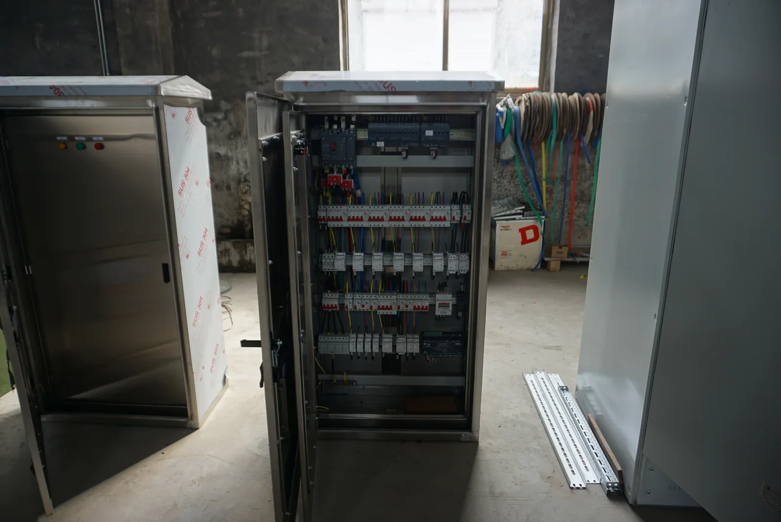
Connect your generator project to our electrical equipment
Our starting point is the auxiliary equipment that needs power or a connection to the project controls. This may include a specified transfer pump, heater, level indication or fault contact. We discuss how those devices connect to a distribution cabinet, control cabinet or auxiliary power source around the selected generator.
The generator model and its operating duty give that discussion useful context. A standby installation and equipment used for longer operating periods can have different auxiliary duty patterns. We use the selected generator and fuel-system information to coordinate our electrical scope with the equipment already defined for the project.
Coordinate pump, heater and control circuits
Auxiliary power
We discuss voltage, phase, frequency and operating demand for each specified pump, heater and control supply. Motor starting and simultaneous operation can shape the source and circuit arrangement, while a heater's operating cycle contributes to the sustained load. Identify which auxiliaries need power before the generator starts and which operate during or after its run.
Signals and operating behavior
Level, running and fault indications need a defined signal type, normal state and destination. We use those details to discuss terminal grouping, labels and the connection to the generator or site controller. Monitoring, automatic control and a shutdown request have different purposes; the project's selected control sequence defines how each is used.
Electrical interface example: auxiliary supply → specified pump or heater circuit; level and operating signals → designated controller and indications.
Relate the fuel arrangement to its auxiliary equipment
Liquid-fuel arrangements
Storage and transfer arrangements can introduce pump power, local level signals and transfer-control interfaces. We discuss the electrical equipment identified in the fuel-system design, including the relationship between the generator controls and any separate transfer equipment.
Gaseous-fuel arrangements
The selected gas-supply equipment may have its own specified electrical controls or status connections. These belong in the auxiliary schedule alongside the generator's requirements. The generator and fuel-system specialists define the fuel path and its operating conditions; we use the resulting device and signal information for our cabinet and power-interface work.
Build a useful auxiliary equipment schedule
We connect the selected equipment references to the electrical details needed for the cabinet arrangement. A schedule keeps a device's supply requirements beside its function and the controller or circuit it connects to.
| Item | Useful project information | Effect on our interface discussion |
|---|---|---|
| Pump or motor | Voltage, phase, frequency, running demand and starting behavior | Power source, circuit arrangement and control-device space |
| Heater | Supply, operating demand and duty pattern | Simultaneous load and sustained circuit demand |
| Level or condition device | Signal type, normal and fault states, connection reference | Terminal groups, labels and controller interface |
| Generator controller | Designated inputs, outputs and operating sequence | Relationship between auxiliary control and generator operation |
The device reference helps keep revisions and replacement choices connected to the actual load. Fuel consumption and operating limits remain associated with the selected generator so changes can be discussed on a consistent basis.
Bring operating duration into the auxiliary duty
The required operating period is useful context for auxiliary equipment. A pump that transfers fuel intermittently has a different duty pattern from a continuously operating device; a heater may operate while the generator is waiting to start. We discuss those patterns when coordinating the auxiliary source, heat-producing equipment and cabinet arrangement.
For stored fuel, nominal capacity and usable capacity describe different quantities. The selected generator's consumption at the intended load and the project's replenishment arrangements shape the fuel-system planning. We use the associated pump and control duties as electrical inputs, with units and operating assumptions clearly identified. This keeps the generator's operating objective connected to the auxiliaries that support it.
Connect local and remote equipment locations
An integral or sub-base arrangement places fuel equipment close to the generating set. A day-tank arrangement creates a local operating supply, while remote storage can introduce separate transfer equipment and longer routes between devices and controls. These locations affect where auxiliary circuits and signals need to go.
We discuss the designated equipment positions, cable routes and local access with your project team. Separating the local panel, generator interface and remote devices in the layout makes terminal identification and entry planning more specific. We also consider the space needed around the selected control and power components, including access for their eventual replacement.
Match the cabinet arrangement to its environment
For our enclosure work, we discuss indoor or outdoor location, moisture, dust, cleaning, ambient temperature and corrosion exposure. Metal substrate, finish, door closures and cable-entry details work together around the selected components. A durable finish also depends on attention to edges, openings and the hardware used in the assembly.
Pump controllers, power supplies and other internal components contribute heat that needs a suitable path out of the enclosure. We relate their space and ventilation requirements to the site conditions. Any specified area classification comes from the project design and shapes equipment selection; the fuel-system specialist defines materials and components in contact with the fuel.
Coordinate the electrical interfaces with your project team
We bring our auxiliary-power and cabinet details into the discussion with the generator supplier and your designated integrator. The useful connection is between a defined operating need and the power circuit, terminal or enclosure detail that serves it.
| Project input | What we discuss for the electrical arrangement |
|---|---|
| Selected generator and auxiliary devices | Supply conditions, loads and equipment references |
| Defined operating sequence | Commands, indications and normal or fault states |
| Installation layout | Cabinet position, cable-entry approach and access |
| Updated device or site requirement | Affected terminals, labels, dimensions and heat conditions |
Keeping these interfaces together helps the project team handle a device change without losing its effect on another assembly. We agree our supplied equipment and associated documents with the project as the arrangement develops.
Prepare electrical documents and delivery information
For the agreed equipment scope, we discuss the outline and mounting information, power and signal connection references, terminal identification and component details needed by your team. Consistent equipment labels help connect the physical assembly to the drawings and the selected auxiliary devices.
Our packing and delivery discussion follows the cabinet configuration and destination. The generator and fuel-system teams manage their specialist equipment requirements alongside this electrical scope. Retaining the agreed equipment references and current drawings gives later maintenance or replacement enquiries a clear starting point, particularly when a pump, controller or signal device changes during the project's life.
Discuss your generator auxiliary interfaces with us
Tell us the generator application and the auxiliary equipment you need to connect. Add the pump, heater or control references, supply conditions, required signals, installation environment and quantity where known. A short description of the intended operating sequence is useful even while some device details are being finalized.
Explore our distribution cabinets, power-supply cabinets and electrical enclosures for the related equipment options. We can then discuss the drawings and interfaces that will help your project team develop the arrangement.