
Power Supply Cabinets
Our power supply cabinets bring power-conversion equipment, protection, distribution and controls into a coordinated layout. We start with the power your equipment needs, then work through the electrical interfaces, cabinet construction and access that make the configuration practical to install and maintain.
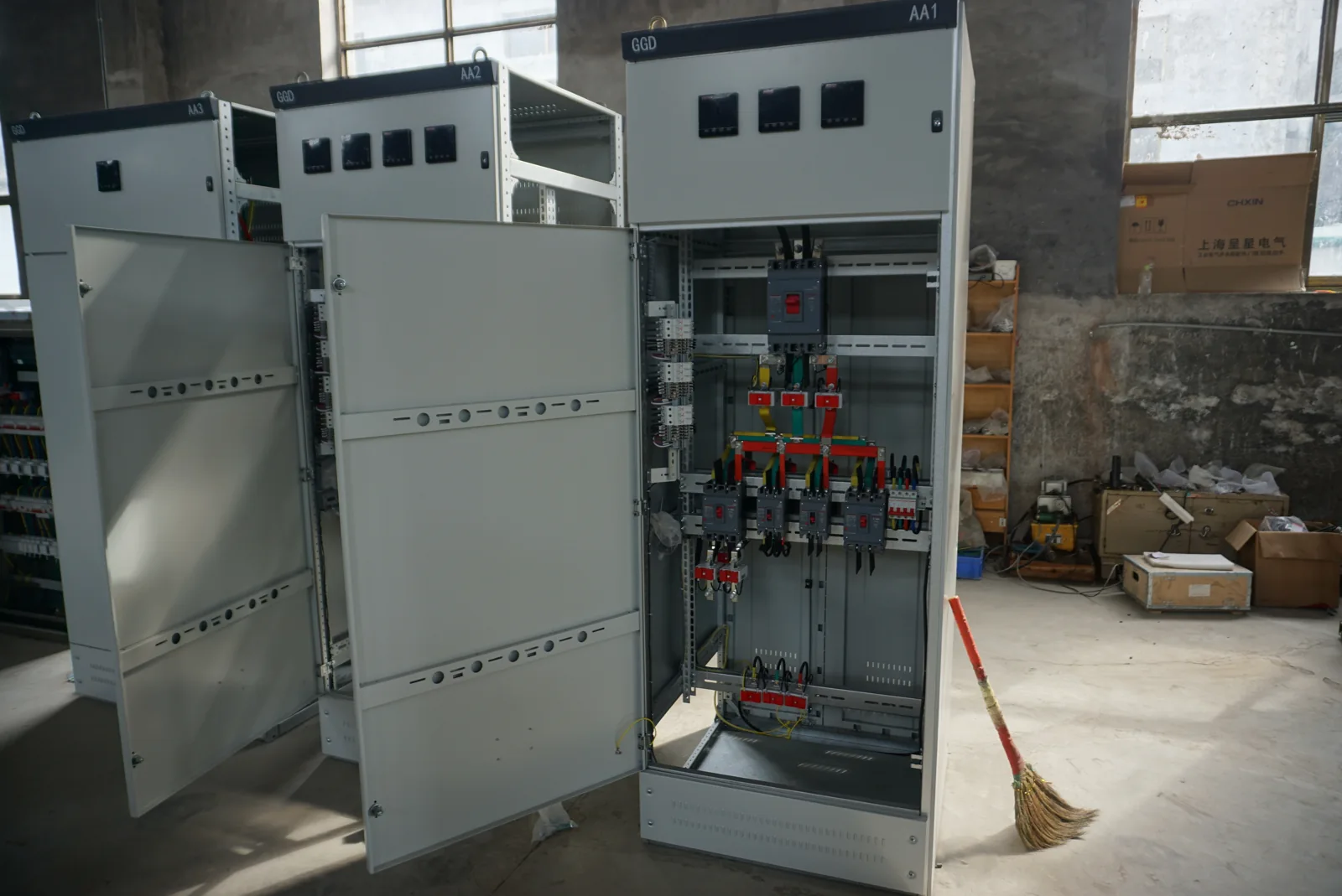
Power conversion organized around your equipment
A machine may need a different AC voltage, a steadier supply or an independent output frequency. We connect that requirement to the surrounding cabinet: incoming equipment, conversion unit, outgoing circuits, terminals, controls and cooling. Bringing these functions into one layout makes their interfaces easier to coordinate and keeps installation space visible from the start.
Complete cabinet or individual power supply?
A DIN-rail DC supply powers a defined load inside a panel; it is one part of the wider assembly. A power supply cabinet organizes that equipment with its electrical and mechanical interfaces. We discuss DC conversion or charging integration separately when the application calls for it; the DC power cabinet page explains those project requirements.
Match the conversion function to the load
| Function | What it does | Application focus |
|---|---|---|
| Transformer-based AC | Changes voltage, with separate windings where isolation is needed | Machine supply voltage, winding arrangement and neutral |
| Regulated AC | Adjusts voltage within a defined operating range | Changing source voltage and equipment tolerance |
| Frequency-converting AC | Provides the required AC output frequency and voltage | Equipment compatibility and test operating points |
| AC-to-DC integration | Connects a selected DC conversion function to the cabinet | Electronics, DC buses or a separately defined charging duty |
We use these functions to build a clear equipment brief. Voltage stabilization and frequency conversion address different supply conditions, even when both sit within a cabinet.
A clear path from incoming supply to outgoing circuits
Functional arrangement: incoming supply → isolation and protection → conversion equipment → outgoing distribution → load. The arrangement shows how the cabinet's functions connect; project drawings define the actual circuits.
We work with the input voltage, frequency, phases and grounding arrangement alongside the required output. Line-to-line and line-to-neutral values remain explicit, especially where the load needs a neutral. Incoming and outgoing terminal locations are coordinated with cable-entry direction and the available installation space. This connects the electrical design to the work of bringing cables into the cabinet, rather than treating enclosure dimensions as a separate decision.
Capacity for continuous operation and changing demand
Running demand describes only part of a supply cabinet's duty. Starting loads, short peaks, standby circuits and equipment operating together determine how the conversion unit experiences the production cycle. We use both the load rating and its sequence to discuss a suitable configuration.
Follow the operating sequence
For example, machine controls may remain energized while the main process load starts and stops. A drive may also return energy during a particular operating state. These conditions influence current capability, output behavior and protection. Separating continuous demand from transient or reverse-power requirements makes the equipment selection more useful than simply increasing its nominal power rating.
Protection that fits the complete power path
The incoming device, conversion equipment, branch protection, conductors and terminals operate as a connected system. Interrupting capability, fault withstand and normal current duty are different characteristics. The complete cabinet configuration must suit the supply conditions; the largest number printed on one component does not describe the whole assembly.
We coordinate cabinet interface information with your electrical team, including the upstream protective device, available fault current and outgoing loads. Where a bypass or alternate source is part of the project, its permitted states belong in the power arrangement and operating instructions. Protective settings and site connections remain part of the approved professional installation process.
Materials and cooling with maintenance in mind
Match construction to the environment
Coated steel and stainless steel have different cost, finish-care and corrosion-selection considerations. We discuss the cabinet's location, moisture, contaminants and cleaning conditions before defining the material and finish. Copper or aluminum conductors also need compatible terminals and an appropriate connection arrangement; conductor choice works together with the electrical and thermal design.
Give heat and service work a clear route
Component losses and ambient temperature shape the cooling arrangement. Ventilation supports heat removal, while greater sealing changes how that heat can leave. Our layout discussions include airflow, doors, filter access and space to remove serviceable equipment, giving both operation and future maintenance a place in the cabinet design.
Useful indications and a practical replacement strategy
Ready, running, output available, alarm and trip indications help operators understand cabinet status. Local and remote commands need a defined authority, feedback and response to lost communication. We organize these functions around the customer's process so an indication, a command and a permission remain distinct.
Where continuity of supply is important, we discuss the load that must remain available and the failures the arrangement needs to accommodate. Shared incoming power, controls or cooling can remain common dependencies in a modular design. Replacement access and spare-unit compatibility are therefore considered alongside any proposed redundancy; energized replacement requires equipment specifically designed and authorized for that operation.
Our cabinet configuration and your project interfaces
| Area | Cabinet configuration | Customer interface |
|---|---|---|
| Power conversion | Selected function, equipment and operating duty | Source data and load behavior |
| Protection and terminals | Internal devices, connections and identification | Upstream protection and site cables |
| Enclosure and cooling | Material, layout and heat-removal arrangement | Environment, access and available space |
| Project information | Agreed drawings, component details and instructions | Installation and acceptance requirements |
We bring these items together in the project discussion and quotation. Consistent equipment identifiers across drawings and terminal schedules help installation teams prepare and maintenance teams locate the right circuit later.
From agreed configuration to equipment handover
We agree the drawing information, inspection items and accompanying records for the selected cabinet before manufacture. The relevant checks follow the configured equipment and its operating functions. Documented component changes remain connected to the final arrangement so the equipment and its records describe the same build.
For day-to-day use, clear status labels and operating instructions help distinguish normal operation from a condition requiring attention. Operators can record an alarm and the load state without opening restricted areas. Qualified personnel handle installation, commissioning and intrusive maintenance using the equipment instructions. Keeping circuit references and replacement identifiers accessible supports orderly service work.
Tell us what your equipment needs to power
Start with the equipment's purpose and the supply available at your site. A nameplate, a short load description or the voltage-conversion requirement is enough to begin the conversation. We can then organize the output requirements, operating cycle and cabinet layout with your team.
As the configuration develops, we discuss quantity, destination, cable approach and transport access. Packing dimensions, handling information and any shipping sections can then be coordinated with the receiving arrangements. If you already have a drawing, mention its type so we can arrange the next exchange.