
Busbar Connection Boxes
We organize busbar connection-box configurations around your incoming supply, outgoing circuits and installation space. Bringing conductors, supports, terminals and the enclosure together creates a clear interface for power connections and future maintenance.
Our configuration discussion establishes the AC or DC duty, supplied connection components, enclosure construction and relationship to external protection. The selected arrangement follows the electrical and environmental requirements of the project.
Bring multiple power connections into an organized assembly
A busbar connection box can join incoming conductors, distribute power to several circuits or provide an interface between equipment sections. We begin with that function, then define the current paths and the parts needed around them. Switching and overcurrent protection are separate functions that can sit within a larger assembly or elsewhere in the system.
| Part | Purpose in the configuration |
|---|---|
| Conductors | Carry the defined phase, neutral or DC current paths |
| Insulating supports | Position the bars and resist mechanical loads |
| Terminals and lugs | Match incoming and outgoing cable connections |
| Enclosure and barriers | Organize access, separation and environmental protection |
| Protection interface | Coordinate the connection assembly with protective equipment |
Shape the connection around AC or DC operation
AC distribution
For an AC project, we discuss voltage, frequency, phase arrangement, neutral requirements and simultaneous demand. These details define the poles and how the box connects to the source and outgoing circuits.
DC power paths
For DC, polarity, voltage range and current direction become central. Batteries, chargers and converters may create several sources or bidirectional paths. The isolation and protection arrangement must account for those paths with devices suited to DC duty. Our battery cabinet page explains the associated module and converter interfaces. Keeping these requirements separate avoids treating an AC connection layout as a universal DC design.
Make every conductor and terminal easy to identify
We coordinate pole positions, terminal numbering and entry direction with the circuit schedule. Phase, neutral, polarity and protective connections each have a defined role; clear identification helps fabrication, installation and subsequent service follow the same arrangement.
Connect the electrical schedule to the physical layout
A conceptual AC path runs from the incoming supply through the assigned phase and neutral connections to outgoing circuits. A DC layout uses identified positive and negative paths, with protective connections defined separately. The layout also accounts for parallel cables, removable covers and access to each connection. Those relationships form the basis of a project-specific drawing.
Consider current, heat and fault forces together
Busbar cross-section is one part of the design. Electrical resistance at conductors and joints produces heat, while the enclosure and surrounding air determine how that heat escapes. The connection surfaces, cable terminations and operating duty therefore affect temperature rise alongside the bar dimensions.
Support the complete current path
A short circuit also creates mechanical forces between conductors. Support material, spacing and fixing arrangements help the assembly withstand those forces within its designed duty. We connect thermal and mechanical requirements with the upstream protection and site conditions; changing a bar size alone does not establish a new rating for the whole box.
Compare conductor materials and connection surfaces
Copper and aluminum
Copper's higher conductivity can support a more compact conductor section for a comparable resistance. Aluminum offers lower mass, while its required section and connection geometry may occupy more space. We discuss those tradeoffs together with the cable material, enclosure envelope and current duty.
Joints and insulating supports
Contact-surface finish, lug construction and compatible hardware matter where current crosses a joint. Dissimilar metals require a connection system intended for that combination. Insulating supports must suit the electrical separation, temperature and mechanical loading. Material grade, surface treatment and support construction belong to the selected assembly rather than being inferred from the appearance of a bar.
Match terminals to the cables arriving on site
We use a connection schedule to align each cable with its terminal, entry face and available bending space. This is particularly useful when one pole accepts parallel conductors or different outgoing circuits approach from different directions.
| Interface | Details that shape the layout |
|---|---|
| Circuit identity | Source or load reference, pole or polarity and terminal number |
| Cable construction | Metal, conductor size, quantity, insulation and outside diameter |
| Connection hardware | Lug arrangement, hole pattern and mating surface |
| Cable route | Entry direction, support points and bending envelope |
Conductor size and cable outside diameter serve different purposes. Both belong in the schedule, with tightening requirements taken from the selected connection components.
Fit the enclosure to installation and service space
We discuss the box together with the cables around it: mounting surface, entry positions, cover-removal direction and nearby obstructions. External cable support helps keep installation loads from being transferred to the terminals.
Exposure and future additions
Indoor contamination, moisture, outdoor exposure and cleaning conditions influence the enclosure, seals and entry accessories. Their arrangement must suit the complete installation. For expansion, identified spare positions and access space can be included in the layout discussion. Physical spare space and available electrical capacity remain separate considerations, so a future circuit needs both to be addressed.
Choose the connection format that fits the application
A connection box concentrates power connections at one location. A busway system carries power along a coordinated route with sections, joints and tap-off interfaces. A distribution cabinet combines circuit distribution with specified switching and protective functions.
We use these functional differences to keep the project configuration focused: a local connection chamber, a routed distribution system and a protected outgoing-circuit assembly each solve a different interface problem.
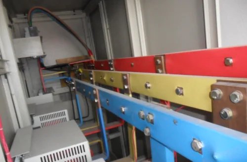

Dedicated panel busbars and comb connectors
A comb busbar or an OEM neutral bar inside a specified breaker panel is a system-specific part. We use the original panel, device and part references to discuss its mating contacts, pole arrangement, fixing points and electrical duty. Matching current or dimensions alone does not establish compatibility across systems. For cabinet component and replacement discussions, include the existing system identification; the connection boxes on this page organize local power interfaces around the selected conductors and terminals.
Keep the layout and connection records aligned
We coordinate the general arrangement, pole layout, terminal schedule and material requirements around the same configuration. Consistent circuit identifiers make it easier to connect the physical assembly with the project drawings and installation records.
Carry the configuration through delivery
The agreed document package and inspection scope link supplied parts to their intended positions. At receiving, covers, insulating supports and terminal hardware should remain protected from damage before installation. Qualified personnel complete the connections and required verification using the equipment instructions. Recording approved changes preserves a clear reference for later work.
Discuss your busbar box configuration with us
Start with the number of incoming and outgoing circuits, the AC or DC application and the available space. We can then organize the discussion around conductor materials, terminal interfaces, cable routes and the enclosure environment. Mention any existing drawings so the relevant details can be exchanged as the project develops.
For replacement or expansion discussions, part references and the existing layout help identify the interfaces that must remain compatible. Component schedules also support maintenance planning, while internal inspection and connection work remain tasks for qualified personnel. Clear configuration records make those later decisions easier.