
Cable Branch Boxes
We shape cable-branch enclosure configurations around the circuits they connect. Voltage class, cable construction, entry direction and site conditions guide the arrangement of terminals, supports, seals and accessible connection space.
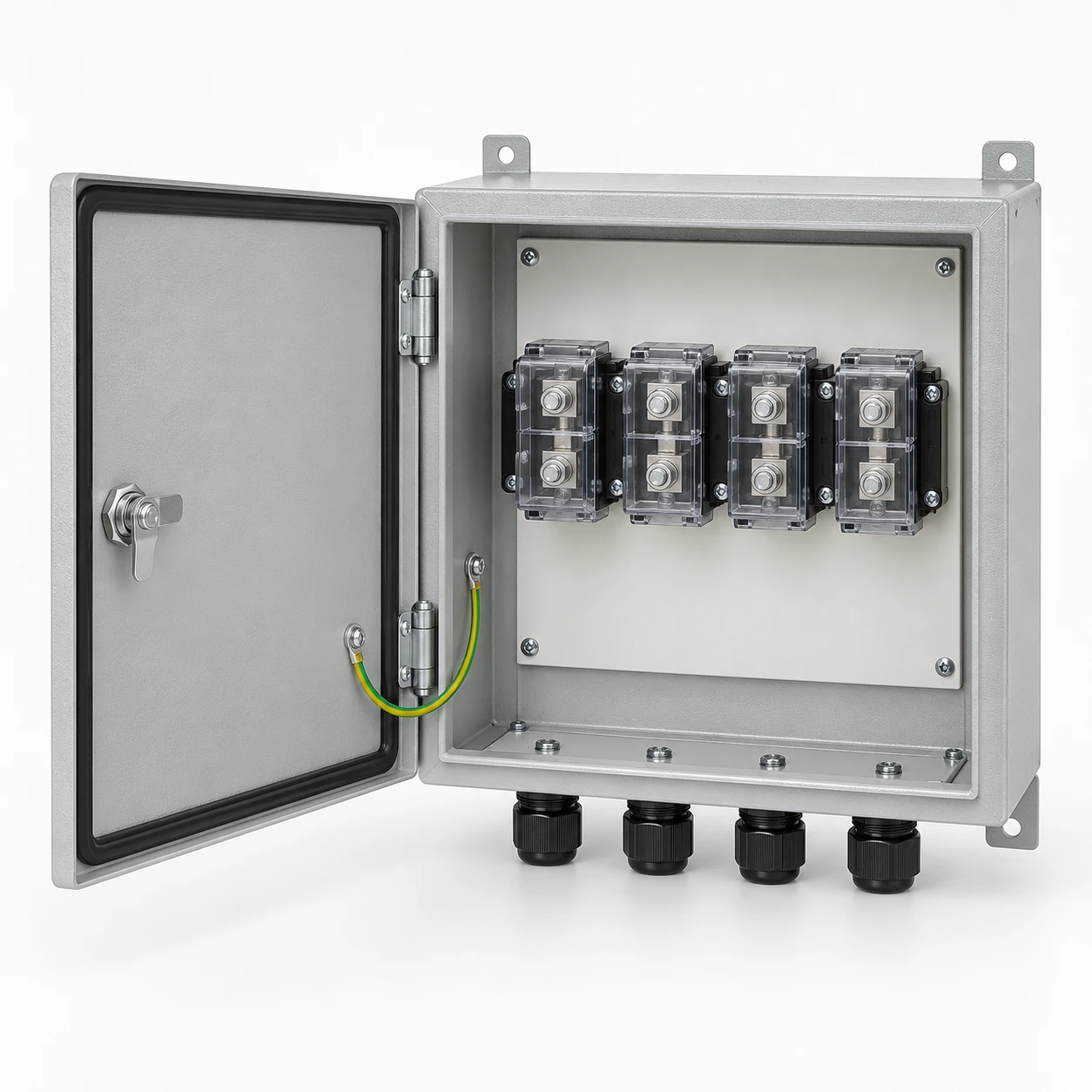
We define the enclosure and connection interfaces with your project team. The selected voltage class, cable accessories and switching or protection functions determine the final assembly and supply arrangement.
Choose a connection arrangement for the voltage class
A cable branch box creates an organized point where incoming and outgoing circuits meet. We begin with the voltage class and the connection function because these determine the accessories, separation and space around the conductors.
| Application | Connection approach | Configuration focus |
|---|---|---|
| Low-voltage branching | Terminals, lugs or busbar connections | Conductor combinations, layout and assembly duty |
| Medium-voltage interface | Project-specified cable accessories and mating components | Insulation geometry and exact accessory compatibility |
| Switched or protected distribution | Connections combined with selected devices | Operating functions and protection coordination |
The actual voltage and AC or DC duty guide this choice, together with the upstream and downstream equipment.
Serviceable connection boxes and encapsulated joints
We distinguish an accessible terminal or busbar box from a cast-resin or other encapsulated cable joint. A serviceable box provides access to its specified connections under the equipment maintenance procedure; an encapsulated joint encloses the connection within the chosen accessory system. Its inspection and replacement method follows that system, which may require replacement of the joint rather than reopening it for reconnection. We discuss the enclosure and selected cable-accessory interfaces together so the installation and future maintenance approach remain clear.
Coordinate branching with switching and protection
Connecting circuits, isolating equipment and interrupting faults are different functions. A passive branch chamber provides a connection point; switching and protective devices perform the additional tasks needed by the system.
Follow every source path
We discuss the source arrangement, continuous current, frequency where applicable and available fault-current information with the project team. Alternative sources or reverse power flow can change the isolation and protection requirements. A project involving switching connects with our switchgear configuration discussion, while our distribution cabinets address the wider arrangement of outgoing circuits.
Translate cable details into a practical layout
We match each circuit to its cable construction and route. Conductor cross-section describes the metal carrying current, while overall diameter determines entry fit and affects the space around the cable. Relevant insulation dimensions serve another purpose when selecting cable accessories.
| Cable detail | Design relationship |
|---|---|
| Circuit identifier and cable count | Connection positions and labeling |
| Conductor metal and size | Terminal or lug combination |
| Overall outside diameter | Entry seal, support and routing space |
| Insulation and screen construction | Cable-accessory interface |
| Entry direction and bending requirements | Termination-zone dimensions |
We retain cable sizes in their original AWG/kcmil or mm² units so the connection discussion stays tied to the actual cable designation.
Match the connector to the complete cable construction
Conductor and termination
The conductor metal, size, construction and quantity must match the selected terminal and lug arrangement. Copper and aluminum cables can require different connection details, especially where dissimilar metals meet. Cable size alone does not describe the complete joint.
Insulation, screen and mating interface
For a medium-voltage interface, insulation material and diameter, screen construction, core arrangement and the exact mating component shape the accessory selection. We coordinate enclosure space around the project-selected accessories. Exact part and interface references keep the arrangement consistent; a similar external size or current label is not a substitute for a compatible connection.
Give the connected cable room to bend and enter
The usable termination zone extends beyond the connector itself. We consider the cable approach, sealing zone, supports, bending envelope and final connection together. A layout that fits a bare connector can still be too restricted once the cable is attached.
Link entry direction to service access
Bottom, side or rear entry affects the route to each termination and its relationship to neighboring circuits. Door movement, removable covers and nearby walls also influence usable space. We bring the selected cable's bending requirements and the accessory installation envelope into the layout discussion so connection positions work in the actual installation.
Select enclosure materials and seals for the location
A steel enclosure provides a structural shell whose thickness, reinforcement and finish can be discussed around mounting loads and exposure. Coatings protect the substrate, including edges and prepared openings. Corrosion-resistant metal choices involve different material and fabrication considerations. We relate these options to the project's environment and access needs.
Make entries part of the enclosure design
Gaskets, cable glands, entry plates and unused-opening closures work as a system. Cable outside diameter and entry geometry determine their fit, while supports manage cable loads. Finish and seal details also affect later maintenance. For a smaller general connection enclosure, explore our electrical junction boxes.
Plan around rain, moisture and mounting conditions
Wall mounting, a raised base and a pit installation expose the enclosure to different water paths and access conditions. We discuss rainfall, washdown, condensation, corrosion and the possibility of standing water alongside the enclosure and cable entries.
Distinguish outdoor exposure from immersion
Protection against rain is a different duty from submersion under water. The intended location therefore matters more than a general outdoor label. Site drainage, base construction and ground levels are coordinated by the responsible project professionals. Drains, vents and other openings also belong in the enclosure configuration so their effect on moisture management is considered together.
Our project drawings connect circuits to physical parts
We organize the configuration around a general arrangement, cable schedule and identified terminal or accessory positions. Matching circuit numbers across these documents helps the project team connect the electrical design with the enclosure layout.
Keep revisions coordinated
A changed cable diameter may affect its entry seal; a different lug can change the connection envelope. Those relationships make revision control useful throughout the project. The agreed material schedule, assembly requirements and inspection scope follow the selected arrangement. Resolving cable dimensions and entry positions before fabrication helps keep the cabinet and site connection details aligned.
Coordinate delivery with the connection work
We discuss packing, accessory identification and the required document package as part of the project arrangement. Clear labels help relate loose seals, supports and connection hardware to their positions in the assembly. Handling space and storage conditions also matter where the enclosure will wait for cable installation.
Protect the interfaces through installation
Enclosure corners, seals and packaged cable accessories need protection from transport and site damage. Qualified personnel complete cable preparation, termination and verification using the selected component instructions and site procedures. The completed cable schedule and connection records then provide a useful reference for operation and later changes.
Discuss your cable connections and future changes
Begin with the system voltage, number of incoming and outgoing cables, installation location and approximate space. We use that overview to develop the configuration discussion, then coordinate cable types, connection accessories, enclosure materials and entry details. Existing drawings can be exchanged as the project progresses.
For replacement or expansion, the installed cable and accessory references help identify which interfaces must be preserved. A changed cable type can affect the connector, support and seal together. Keeping these identities alongside circuit labels and layout revisions makes maintenance and future additions easier to plan.