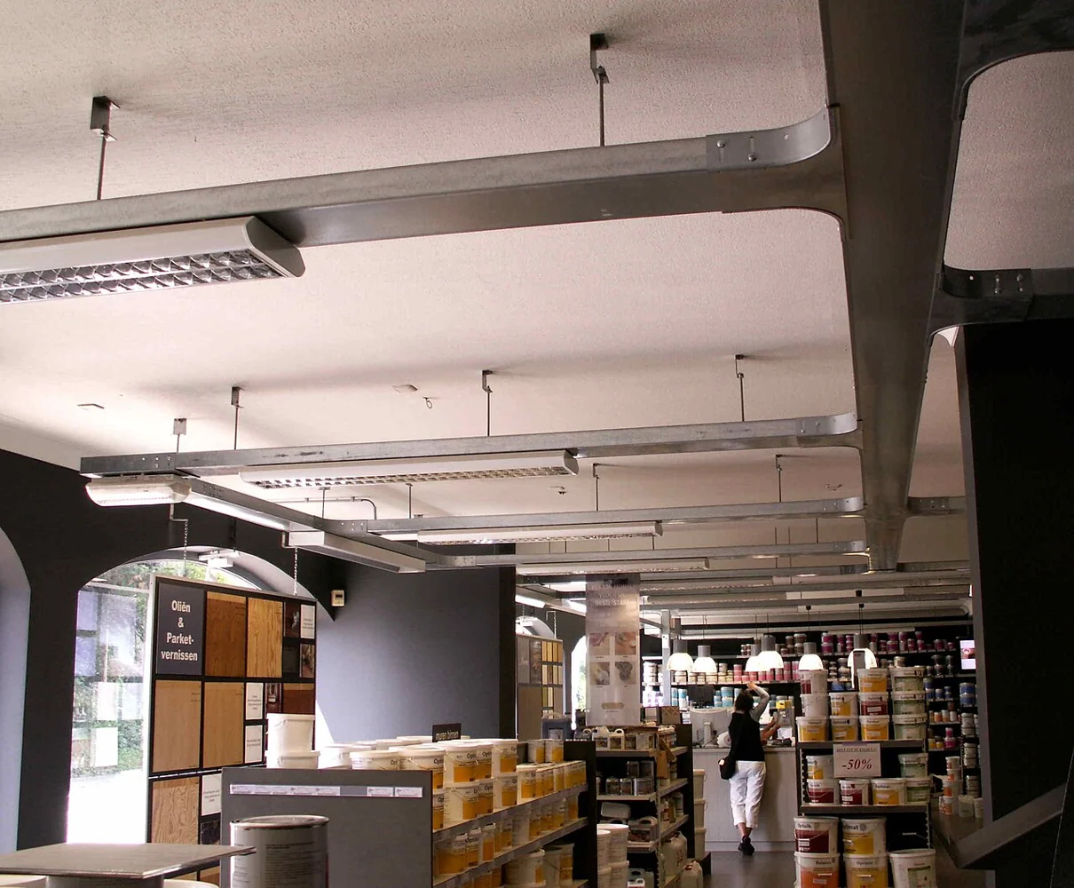
Cable Tray and Cabinet Cable-Routing Interfaces
We work with project teams to connect cable-routing requirements to our cabinet and enclosure interfaces. Cable size, route geometry, supporting structure and installation conditions guide the discussion, helping bring tray, ladder, wire-mesh or trunking routes into a practical cabinet-entry arrangement.
Compare the cable-containment forms
We discuss the route form alongside the cables and the space around our distribution cabinets. Each form combines support, access and ventilation differently, which affects both the main run and the approach to the equipment.
| Form | Structure | Routing and access characteristics |
|---|---|---|
| Ladder | Side rails with spaced rungs | Open ventilation and access; rung support coordinated with the cable |
| Perforated tray | Supporting bottom with openings | Distributed cable support with drainage and ventilation openings |
| Wire mesh | Open wire basket | Visible routes and adaptable transitions with matching fittings |
| Enclosed trunking | Channel with cover | Covered routing with access and heat dissipation planned together |
The complete arrangement, including covers and entries, determines how the route meets its environmental requirements.
Connect cable information to the route drawing
Cable outside diameter, mass per length, service and construction help us organize the interface discussion. The route drawing adds elevations, branches, crossings and destination cabinets. Together they show where cable groups share a path and where power or signal circuits need separate treatment.
Access and future additions
We discuss the space needed for inspection, pulling and replacement alongside planned expansion. Empty width alone does not establish spare structural or electrical capacity. Recording future cable types and quantities gives the project designer a useful basis for fill, loading, separation and thermal decisions as the route develops.
Match the section to its loads and support spacing
Cable weight becomes a distributed load along the route. Covers, accessories and any relevant environmental or concentrated loads also enter the structural assessment. Section shape and support spacing influence both strength and deflection, so width or metal thickness alone cannot describe the complete load capability.
Straight runs and local supports
We coordinate the proposed route with the project's support design, including fittings and changes in direction. Longer spans can change deflection and loading requirements; bends and vertical transitions can need different support details from straight sections. The selected system's section data and support arrangement provide the basis for those decisions.
Choose materials for exposure, handling and connections
| Material | Useful characteristics | Design considerations |
|---|---|---|
| Galvanized steel | Structural strength with a protective zinc coating | Coating selection, damaged or fabricated areas and hardware compatibility |
| Stainless steel | Corrosion resistance suited to the selected alloy and exposure | Cleaning chemicals, surrounding metals and compatible fittings |
| Aluminum | Lower material mass for handling and support planning | Section stiffness, joints and dissimilar-metal interfaces |
We discuss moisture, chemicals, cleaning and indoor or outdoor exposure with the route requirements. Material grade and finish are selected for that environment; visible appearance alone does not describe corrosion behavior or structural performance.
Make bends and branches workable for the cables
Start with the cable's bend requirement
The cable's permitted bend radius shapes horizontal turns, vertical bends and drops into equipment. We bring those transitions into the route discussion early, including tees, reducers and obstacles that can affect the usable path.
Practical geometry also leaves room for installation and later cable replacement. A centerline on a drawing may fit between equipment while the actual bend and cable bundle need more space. Coordinating fitting dimensions with the cabinet approach helps reduce clashes at the entry and keeps power and signal routes aligned with the project's separation requirements.
Coordinate mechanical supports and electrical continuity
The support arrangement connects the route to the building or equipment structure. We work with the project team on attachment locations, vertical-run requirements and any movement provisions, keeping the route geometry aligned with the responsible structural designer's assessment.
Mechanical joints and electrical bonding serve related but distinct purposes. A splice that joins two sections mechanically does not by itself establish every protective-conductor requirement. The electrical designer determines the continuity and bonding arrangement for the selected system, including separate bonding components where needed. Keeping these items in the route schedule helps avoid treating them as incidental site accessories.
Bring the cable route into the cabinet
We coordinate cable approach, bend space, gland or transit positions and the cabinet entry plate. Support near the entry keeps cable weight and route loads from being transferred to an enclosure without being included in its design.
Inside the cabinet, cable length and terminal position determine the space needed for dressing and termination. The entry arrangement also works with sealing and service access. Linking the route drawing to our enclosure configuration helps the outside cable path and inside equipment layout meet at a usable interface.
Our route and component schedule
| Component group | Information organized by route |
|---|---|
| Straight sections | Form, dimensions, lengths and quantities |
| Fittings | Bends, tees, reducers and equipment drops |
| Accessories | Covers, dividers, edge protection and joints |
| Supports and bonding | Brackets, fixings and required continuity components |
We use route tags and drawing revisions to connect quantities with cabinet-entry references and the agreed project supply arrangement. Where finish or fit samples help resolve a detail, we discuss them alongside the written requirement. Later component changes can then be assessed for geometry, compatibility and appearance against the same route.
Plan lengths, identification and later route changes
Section lengths affect transport, packing and movement through the site. We discuss bundle dimensions, finish protection and loose-fitting identification with the project arrangement, keeping the component schedule useful for receiving as well as ordering.
Clear route identification helps site teams reconcile parts with the installation drawing. Later additions need the same attention to supports, joints, corrosion and total cable loading. Updating the route schedule after a change preserves a useful maintenance reference. Installation and remedial work follow the selected system documents and the site's professional procedures.
Discuss your cable route and cabinet interfaces
Send a route sketch or describe the cabinets and cable groups you need to connect. Available cable sizes, load information and site conditions help us develop the discussion of route form, material and entry arrangement.
As the layout develops, we can organize support locations, fitting requirements, finish or sample needs and packing constraints with your team. The aim is a practical route that reaches the cabinet with room for support, bending and termination.