
Multi-Meter Enclosures
We configure multi-meter enclosures around the users and shared services they support. Clear meter positions, coordinated incoming and outgoing connections, and practical access make the assembly easier to identify, install and manage as the project develops.
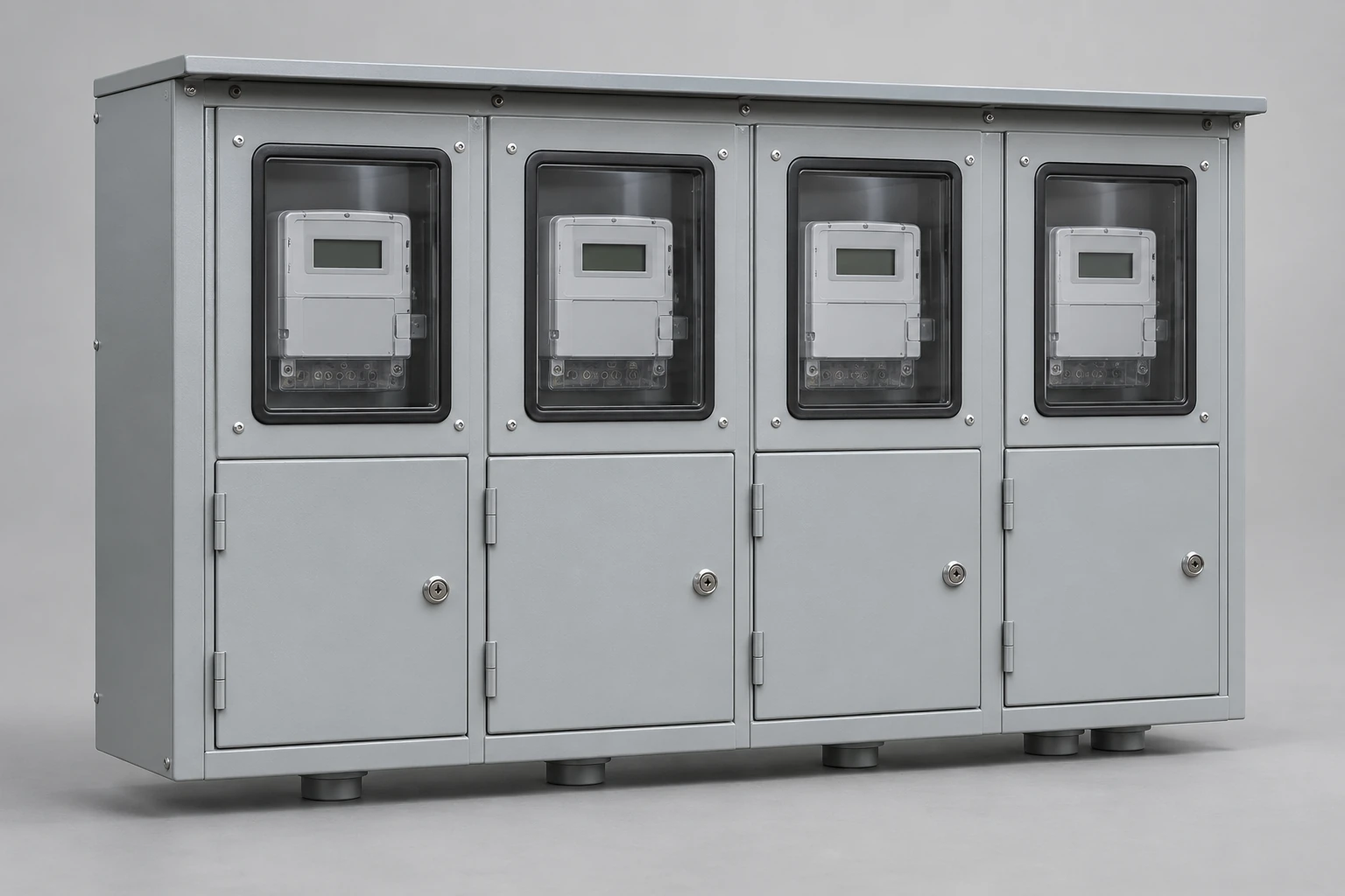
Our project configuration defines meter positions, common supply arrangements, fitted components and enclosure construction together. Utility revenue metering and private submetering follow their respective service and measurement requirements.
Organize individual users and shared building services
A multi-meter enclosure brings several measurement positions into a coordinated layout. Apartments, commercial units and multi-user sites may need separate user circuits alongside common lighting, pumps or other shared equipment. We use those different loads to organize the meter and outgoing-circuit arrangement.
Revenue metering and private submetering
Utility revenue meters follow the serving utility's service and access requirements. Private submeters support internal measurement, allocation or monitoring within the project. The intended use influences meter selection, compartment access and documentation. Bringing that purpose into the initial discussion helps align the enclosure with how the building will operate.
Define positions, phases and terminals independently
The number of meter positions, sometimes described as gangs, identifies how many locations the enclosure provides. It does not determine the phase arrangement or common incoming capacity. We keep those configuration choices separate so each position matches the circuit it serves.
Phase and conductor interfaces
A position may have single-phase or three-phase requirements within the selected service arrangement. Terminal construction is another detail: double-lug describes a connection feature, not two meter positions. The actual terminal design determines the permitted conductor materials, sizes and combinations.
Our position schedule connects meters to circuits
We use a permanent position ID to connect the meter location, outgoing circuit and served unit. The equipment identifier stays consistent even when a tenant or account name changes, making the arrangement easier to manage over time.
| Schedule field | Role in the layout |
|---|---|
| Position and circuit ID | Connects the meter, labels and served unit |
| Voltage, phase and wires | Defines the electrical interface |
| Meter form and mounting | Sets the space and connection arrangement |
| Demand and duty | Contributes to the shared-load assessment |
| Outgoing connection | Coordinates cable routing and protective functions |
| Occupied, spare or shared use | Identifies present and future purpose |
Match the common supply to simultaneous demand
The incoming section, common conductors and neutral arrangement serve the combined operating load. Their duty depends on simultaneous demand, phase allocation, temperature rise and fault conditions. Adding the labels on individual meter positions does not by itself establish the usable capacity of the complete assembly.
Include shared loads and future occupancy
We connect the position schedule with the project's demand assumptions and upstream protection. Common lighting and building equipment remain visible as their own circuits, while future occupancy can change both total demand and its distribution across phases. These relationships guide the incoming connections and common-bus layout.
Separate common, metering and outgoing areas clearly
A useful functional path is common incoming supply → individual meter positions → identified outgoing circuits. The required disconnects and protective devices sit at the locations defined by the service design. We translate those functions into compartments, barriers, doors and cable routes.
Use the space around each meter
Meter mounting, terminal access and outgoing cable bends need space within the same position. Common conductors and shared access areas need their own arrangement. Where the project combines a meter and service disconnect, our meter-main combination page explains the additional interface considerations.
Bring conductor and enclosure choices into the layout
We discuss common-bus conductors, terminal materials and joint surfaces alongside insulating supports and enclosure construction. Conductor material affects section size and connection details; joints and the surrounding enclosure influence the way heat leaves the current path. Supports also maintain the planned conductor positions.
Enclosure structure and finish
Metal thickness, reinforcement, door geometry and surface treatment can be coordinated around mounting loads, exposure and maintenance. These choices shape the physical assembly while the electrical design defines its operating duty.
Keep identification and access clear throughout use
We coordinate permanent position labels with outgoing circuit references and the served units. This creates a consistent link between the physical meter location and the project schedule, rather than relying on the sequence of doors alone.
Reading and controlled access
Utility-sealed areas, common compartments and permitted user controls need clearly defined boundaries. Door movement, meter visibility and seal positions follow those access requirements. Professional meter installation and sealing follow the applicable utility and project procedures. Confirming the installed meter-to-circuit mapping completes the identification system before the arrangement is handed over for use.
Plan additional meter positions with a defined purpose
We discuss future positions alongside wall space, cable approach and shared capacity. The word spare can describe several different preparations, each with a different effect on later work.
| Provision | What the configuration addresses |
|---|---|
| Empty location | Physical space for a later equipment arrangement |
| Fitted meter position | Specified mounting and connection components already included |
| Future module area | Compatible interfaces and room for a later section |
Each option still needs the future demand, phase distribution and common supply considered when the additional load is defined.
Coordinate project delivery and handover information
Our configuration discussion connects the general arrangement, circuit diagram, position schedule and component references. For assemblies delivered in sections, consistent section numbers and packing references help the receiving team relate each part to the layout.
Carry revisions into the final records
Changes to meter count, shared services or outgoing cables are reflected in the agreed project information. Doors, seals and mounting parts need protection during transport and storage. The applicable installation checks, labels and final circuit mapping stay with the completed records, giving the operating team a clear starting point for future maintenance and alterations.
Discuss your meter positions with us
Tell us how many users and shared services the project includes, whether the metering is utility or private, and where the enclosure will be installed. We can begin the layout discussion with that overview, then develop the meter interfaces, supply arrangement, access and expansion requirements.
Existing plans and utility details can be exchanged as the configuration progresses. For a replacement project, the current position IDs and available mounting space help connect the new arrangement with retained circuits. Our aim in the configuration discussion is a clear relationship between users, meters and outgoing connections.