
Electrical Cabinet Accessories
We coordinate cabinet accessories around the parts they connect. Door hardware, equipment supports and cable-entry fittings work best when their dimensions, materials and mating surfaces are considered together.
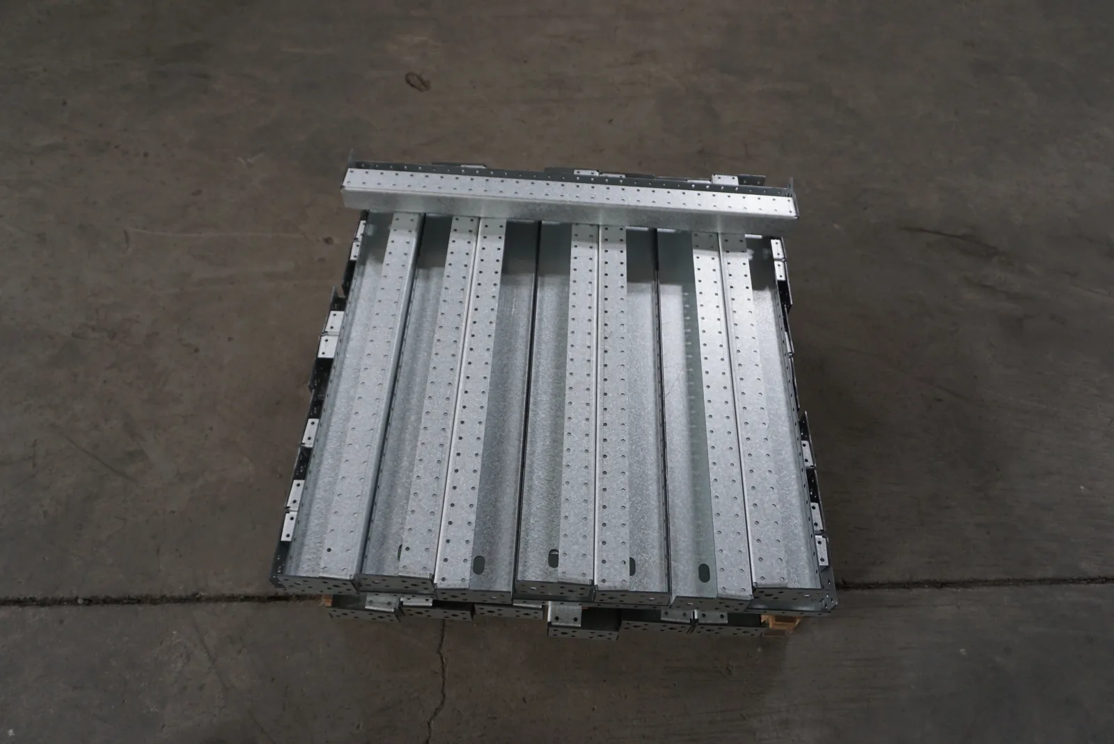
Our accessory discussions cover the cabinet arrangement, retained parts and required function. We define the proposed part references, materials and kit contents with the project configuration.
Select accessories by their role in the cabinet
Our cabinet projects bring together access hardware, equipment supports, cable entries and sealing parts. Organizing them by function helps connect each part to the drawing and makes the required quantities easier to establish.
| Accessory | Key interface | Effect on the cabinet |
|---|---|---|
| Hinge | Axis, fixing pattern and handing | Door support and movement |
| Latch or handle | Cutout, reach and compression | Closure and seal contact |
| Plate, rail or bracket | Profile, fixing points and load position | Equipment support and usable space |
| Gland or entry fitting | Thread, panel thickness and cable diameter | Cable retention and sealing |
For meter-specific doors and fittings, see our meter-box accessories.
Connect the part to its cabinet and mating components
We start with the cabinet reference and the accessory's function. A part number, drawing revision or clear photograph can help establish the arrangement before detailed dimensions are available.
New cabinet fittings
For a new enclosure, the hardware and its cutouts can be coordinated together. This gives the door, frame and mounting layout a shared dimensional basis.
Matching an existing arrangement
For replacement selection, the retained door, frame, latch or bracket also matters. We discuss these mating components alongside the proposed part, using dimensions with clear reference points and units. Concealed measurements belong with authorized personnel familiar with the equipment.
Match the control cabinet key and lock profile
A control cabinet key needs the correct profile and size for the lock insert. The lock reference and documented profile give us a useful starting point for discussing a matching key or a different lock arrangement.
We distinguish the key, lock insert, handle and complete closure assembly because each connects to different parts. A multi-profile key includes particular interfaces; the number of profiles does not establish compatibility with every cabinet. Where keys are controlled, ordering and use follow the site's access procedure. These details keep the inquiry focused on the part actually required.
Coordinate door movement, load and closure
We review hinge center spacing, fixing pattern, axis position and door handing together. Door weight includes fitted instruments or controls, and its distribution affects the load carried by the hinges and their attachment points.
Handles and latches have a different set of interfaces: panel cutout, mounting thickness, reach and engagement with the frame. Compression influences how the gasket contacts the sealing surface. A latch that reaches the frame can still apply an unsuitable compression to the selected seal.
A dimensioned sketch linking the fixed frame, moving door and engagement point helps resolve these relationships before hardware is specified.
Arrange plates, rails and brackets around equipment loads
Mounting plates provide an equipment surface, while rails organize compatible devices and brackets connect parts at particular positions. We coordinate usable dimensions, fixing patterns and access behind removable components with the enclosure layout.
Load distribution matters as much as the total weight. A component mounted away from its support can apply a bending load that differs from equipment positioned close to the fixing points. Rail profile, span and fastening arrangement therefore belong in the selection.
Terminal access, wire ducts and component-removal space remain part of the layout after the supporting hardware is fitted.
Match entry threads and the cable outside diameter
We treat the enclosure connection and cable connection as separate interfaces. Thread designation, pitch, length and plate thickness define how an entry fitting attaches to the cabinet. A threaded opening and a locknut arrangement need different assembly details.
The cable's outside diameter and construction define its fit within the selected sealing and retention range. Similar thread diameters do not make metric and inch thread forms interchangeable, and a suitable thread alone does not establish cable fit.
Entry direction, unused-opening closures, cable supports and any shielding connection complete the schedule. Including these items early helps avoid missing small parts during cabinet assembly.
Consider contact surfaces and environmental exposure
We discuss accessory materials and finishes with the cabinet environment. Coated metal hardware needs protection where the finish may be disturbed; corrosion-resistant materials still need a grade and finish appropriate to the exposure. Dissimilar mating metals also deserve attention where moisture can reach their contact surfaces.
Seals need suitable temperature and chemical resistance as well as the correct section and compression. Changing a gasket or latch can alter the sealing behavior even when the door still closes.
Metallic doors, panels and entry parts may also form part of the protective bonding arrangement. The completed electrical design determines those connections and how substitutions affect them.
Build a clear part and kit schedule
We organize the proposed hardware by part reference, revision and quantity per cabinet. Fasteners, washers, seals, keys and brackets are identified alongside the main component so kit contents are clear.
The schedule distinguishes supplied items from retained mating parts. That relationship is useful when several cabinet sizes use similar-looking hardware with different dimensions. Drawing checks or sample matching can be discussed where a project needs them, with the purpose and scope agreed in advance.
Keeping the selected references with the cabinet drawing also makes later quantity changes easier to calculate.
Keep packing and repeat orders connected to the drawing
Part labels and cabinet references help the receiving team sort hardware into the correct assemblies. Quantity and condition checks are simpler when the packing list follows the same kit schedule used for the order.
Installation follows the selected component and cabinet instructions. Work involving electrical access, protective connections or disturbed seals belongs with qualified personnel for that installation.
For repeat orders or replacement selection, the final fitted reference and drawing revision provide a useful starting point for discussion. Changes to the door, mating hardware or operating environment should be included so the earlier configuration can be reviewed in context.
Discuss your cabinet accessory requirement
Send the cabinet or part reference, accessory function and quantity. A drawing or photograph can help us identify the next dimensions needed.
For door hardware, include handing and hinge or latch details. For mounting parts, include the equipment load; for cable entries, include the thread and cable outside diameter. We can then discuss the matching interfaces and proposed kit contents.