
Control Transformers for AC Control Circuits
We configure control transformers for AC auxiliary circuits serving contactors, relays, solenoids and other machine controls. We bring together the required control voltage, continuous demand and short coil-pickup events, then coordinate the transformer with the available panel space and thermal conditions.
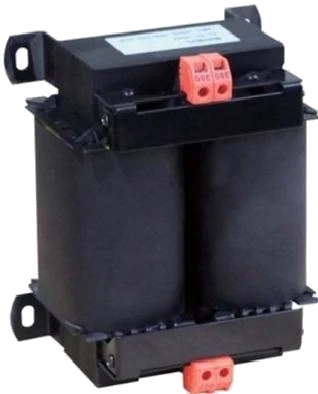
Power for the machine's AC control circuit
Our control transformers establish the AC voltage needed by auxiliary devices within industrial equipment. The control circuit supports switching and actuation, while the main motor or process load follows its own power path. Keeping these duties distinct gives the transformer a clear role in the machine design.
A coil can draw a brief pickup demand that is much higher than its subsequent holding demand. We therefore consider how the devices operate, as well as how many are installed. This connects capacity selection to the actual sequence and helps address voltage behavior when the controls need to act.
Coordinate AC and DC control-voltage domains
A transformer supplies AC at the source frequency. A PLC, sensor or other device requiring DC needs a suitable conversion stage, with its own startup and output requirements. We organize these functions separately in the power arrangement so each load receives the intended supply.
A clear auxiliary-power path
A cabinet may use a transformer for AC coils alongside a DC power supply for electronics, or feed a separately selected conversion stage from a transformer. The chosen arrangement determines terminal groups, protection interfaces and space. Our control cabinet work brings these voltage domains into an understandable layout for the equipment team.
Build the load schedule around pickup and holding demand
Holding, or sealed, VA describes an applicable coil after pickup. Pickup VA describes the initial energization event. We use the selected devices' data to organize the load schedule, including auxiliaries that stay energized throughout the machine cycle.
| Load group | Useful device data | Configuration focus |
|---|---|---|
| Contactor coils | Voltage, frequency, pickup and holding VA | Starting events and retained load |
| Relays and solenoids | Demand, quantity and operating cycle | Simultaneous actions and repetition |
| Other AC auxiliaries | Continuous and startup demand | Base load present during coil pickup |
The schedule turns individual device ratings into a picture of the complete control circuit.
Account for the demanding point in the sequence
Holding loads plus a new pickup event
Consider an illustrative machine sequence in which one contactor is already energized when several solenoids operate together. The transformer supplies the existing holding load and the new pickup demand at the same time. The same installed devices can create a different requirement when they energize separately.
We discuss these events with the machine team, including their duration and repetition. The result is a selection basis tied to the real cycle rather than a sum of holding values alone. Keeping that sequence with the load schedule also makes later circuit additions easier to assess.
Maintain the voltage needed for coil operation
Pickup demand can cause a temporary secondary-voltage dip. The relevant condition combines the minimum primary voltage, the loads already energized and the new coil event. We consider that condition alongside the connected devices' acceptable operating voltage, rather than judging the circuit from nominal voltage alone.
Winding impedance and the downstream cable path both affect the voltage available at the device. The measurement location therefore matters when discussing pickup performance. We align any project-specific voltage assessment with the actual device terminals, operating sequence and repetition rate, giving the project team a practical basis for the selected configuration.
Coordinate winding construction and electrical connections
Voltage and frequency configuration
We develop the primary and secondary arrangement around the stated supply frequency and control-voltage requirement. Terminal identification, any requested connection taps and winding arrangement are brought together in the connection drawing. This keeps the equipment information clear across the transformer and panel documentation.
Core, conductor and insulation
Core design supports the magnetic duty; conductor dimensions and resistance influence losses and voltage behavior under load. Copper and aluminum involve different cross-sections and terminal considerations. The insulation system, temperature-rise requirement and available cooling work together in the thermal design. We discuss these choices against the control circuit and installation rather than selecting a material in isolation.
Make room for connections, cooling and replacement
Our layout discussion includes mounting points, terminal access, cable approach and the space needed to replace the transformer. A device that fits the available footprint may still leave too little room for a practical connection or service route. These allowances are particularly useful in compact machine panels.
The transformer also adds heat to the cabinet. Nearby drives, contactors and power supplies contribute to the same internal environment, so location and ventilation paths matter. We coordinate the mounting arrangement with the wider cabinet cooling requirements, whether the transformer is installed within a panel or discussed with a separate housing.
Our manufacturing and configuration documents
Our wire and foil winding capabilities, vacuum pressure impregnation and high-temperature ovens support the production of winding and insulation assemblies. Core-loss and interturn testing, load equipment and temperature monitoring provide tools for our manufacturing and technical work.
We connect the selected transformer to its load-schedule revision, nameplate, terminal diagram and outline drawing. Agreed inspection items reflect the project configuration, including any specified pickup-voltage assessment. The project electrical designer coordinates primary and secondary protection with the complete control circuit. Consistent equipment identifiers keep those design and production documents connected through cabinet assembly.
Support delivery and later control-circuit changes
We discuss packing, handling and mounting information alongside the equipment documents needed by the receiving and panel teams. The connection drawing and load basis help the machine builder integrate the transformer into the intended sequence rather than relying on nominal VA alone.
After installation, a new coil, changed sequence or additional auxiliary can alter both continuous demand and pickup behavior. Retaining the device schedule makes that change visible. Qualified personnel investigate abnormal operation and assess circuit changes using the current drawings; the original configuration remains a useful reference for that work.
Discuss your control transformer requirement
Tell us the available supply, required control voltage and the devices you want to operate. Device references or nameplates are a useful starting point if a complete VA schedule is not yet available. We can work through the holding and pickup information with your team as the design develops.
Add the operating sequence, frequency, available mounting space and environment. For replacement equipment, include the existing transformer identification and describe any planned circuit changes. We use this information to focus the discussion on the electrical duty, physical arrangement and project documents.