
ZFSO Three-Phase Autotransformers
Our ZFSO series includes 23 three-phase autotransformer models from 3 to 500 kVA. We connect shared-winding voltage conversion with your machine supply, operating load and installation space, helping you select a practical interface between the incoming power and your equipment.
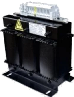
Explore our 23 ZFSO models
Our ZFSO model range runs from 3 to 500 kVA. The table brings each model's capacity, voltage designation, enclosure dimensions and weight into one view, making it easier to connect an electrical requirement with the space available beside a machine or inside a power-equipment area.
Move from a model to your application
Choose a model row to include its identification and capacity in your inquiry. We then work through the connected equipment, operating cycle and installation requirements with you. For a replacement, the existing nameplate and mounting arrangement help us understand the electrical and mechanical interfaces. For a new production line, the load schedule shows which machines run or start together.
| Model | Capacity (kVA) | Voltage | Enclosure dimensions (mm) | Weight (kg) | Inquiry |
|---|---|---|---|---|---|
| ZFSO-3 | 3 | 380V/220V | 240 × 360 × 340 | 20 | |
| ZFSO-5 | 5 | 380V/220V | 240 × 360 × 340 | 23 | |
| ZFSO-6 | 6 | 380V/220V | 270 × 410 × 370 | 30 | |
| ZFSO-8 | 8 | 380V/220V | 270 × 410 × 370 | 34 | |
| ZFSO-10 | 10 | 380V/220V | 270 × 410 × 370 | 37 | |
| ZFSO-12 | 12 | 380V/220V | 300 × 450 × 420 | 47 | |
| ZFSO-15 | 15 | 380V/220V | 300 × 450 × 420 | 52 | |
| ZFSO-20 | 20 | 380V/220V | 300 × 450 × 420 | 57 | |
| ZFSO-25 | 25 | 380V/220V | 350 × 500 × 500 | 77 | |
| ZFSO-30 | 30 | 380V/220V | 350 × 500 × 500 | 83 | |
| ZFSO-40 | 40 | 380V/220V | 350 × 500 × 500 | 93 | |
| ZFSO-50 | 50 | 380V/220V | 450 × 600 × 580 | 123 | |
| ZFSO-60 | 60 | 380V/220V | 450 × 600 × 580 | 135 | |
| ZFSO-80 | 80 | 380V/220V | 450 × 600 × 580 | 145 | |
| ZFSO-100 | 100 | 380V/220V | 450 × 680 × 710 | 198 | |
| ZFSO-120 | 120 | 380V/220V | 550 × 800 × 800 | 275 | |
| ZFSO-150 | 150 | 380V/220V | 550 × 800 × 800 | 296 | |
| ZFSO-200 | 200 | 380V/220V | 600 × 900 × 900 | 360 | |
| ZFSO-250 | 250 | 380V/220V | 600 × 900 × 900 | 420 | |
| ZFSO-300 | 300 | 380V/220V | 1050 × 750 × 1400 | 560 | |
| ZFSO-350 | 350 | 380V/220V | 1050 × 750 × 1400 | 610 | |
| ZFSO-400 | 400 | 380V/220V | 1050 × 750 × 1400 | 700 | |
| ZFSO-500 | 500 | 380V/220V | 1200 × 800 × 1500 | 820 |
No matching model. Clear the search or describe your required capacity in an inquiry.
Configure the source and load connections with us
We establish the connection around the available supply and the equipment's required input. Our table uses the voltage designation 380V/220V; the project schedule identifies the source and load roles, line-to-line or line-to-neutral basis, connection direction and terminal currents for the selected unit.
| Interface | What we coordinate | Why it matters |
|---|---|---|
| Incoming source | Voltage, phase, frequency and operating variation | Defines the conditions applied to the winding |
| Equipment input | Required voltage, current and operating tolerance | Connects the ratio to the actual load |
| Winding connections | Connection direction, terminals and current ratings | Gives the installation a clear electrical arrangement |
| Project changes | Revised supply or equipment duty | Keeps later adaptations tied to the selected construction |
Connect neutral, grounding and protection requirements
We discuss the load's neutral requirement with the source arrangement at the beginning of configuration. A three-phase machine may use only line conductors, while its auxiliary circuits may also need a neutral. The winding connection and terminal provision need to suit that combination.
Coordinate the transformer with its feeder
The shared winding maintains an electrical connection between supply and load. We coordinate terminal identification and the relevant equipment data with the project's grounding and protection design, including cable interfaces and any required fault or energization information. Qualified electrical personnel establish the site protection, bonding and installation arrangement using the selected unit's connection drawing. Clear terminal access and conductor identification also make later inspection more practical.
Size the transformer around running and starting demand
We consider continuous demand, motor starts, repeated switching and the sequence of connected loads together. Starting current and simultaneous machine operation can impose demands that a simple sum of running power overlooks. Rectifiers, drives and other nonlinear loads can add heating through nonsinusoidal current, so their operating characteristics are part of our capacity discussion.
Frequency and thermal duty belong together
A transformer retains the supply frequency. We therefore include frequency alongside voltage when configuring the magnetic and thermal design. Ambient temperature, altitude, ventilation and daily operating hours also influence the intended duty. Where the equipment requires a different frequency, we can discuss our AC power supplies alongside the voltage requirement.
Balance the core, conductor and insulation design
We consider the magnetic core, winding conductor and insulation as one thermal and electrical design. Core material and flux conditions influence no-load loss; conductor resistance contributes to load loss. Copper and aluminum have different conductivity and density, so conductor cross-section, winding space and terminal connections must be considered together when discussing a material requirement.
Give generated heat a practical path out
Insulation separates conducting parts while interacting with heat transfer and winding support. Air passages, enclosure openings and the installation environment influence how heat leaves the assembly. We coordinate these choices with the required duty and space. Loss values and temperature rise describe different aspects of performance: one concerns dissipated energy, while the other connects that heat with the operating conditions.
Fit our ZFSO transformer into your installation
We use the table dimensions and weight for initial planning, then develop the arrangement around the chosen construction. The project drawing identifies dimension directions, mounting points, cable entry and terminal access, bringing the electrical choice into the actual machine or distribution layout.
Plan both installation and continued access
Cable bending space, enclosure opening and ventilation clearances all sit beyond the basic equipment outline. We discuss the receiving route, supporting structure and handling arrangement as part of delivery preparation. Equipment weight and packed shipping weight serve different planning needs; the packing information connects those details with unloading and movement to the final location. Inspection access remains part of the layout after the unit is installed.
Match our power equipment to the job it performs
We discuss ZFSO for machinery and industrial equipment that need voltage adaptation while sharing an electrical connection with the source. Typical project conversations include new machine integration, equipment relocation and coordinated power supplies for a production area. The required voltage ratio, duty and system arrangement determine the configuration.
Separate voltage matching from voltage regulation
A fixed-ratio transformer follows changes in the incoming supply through its ratio. If the main problem is sustained incoming-voltage variation, our voltage stabilizers address a different operating need. Our autotransformer range explains the wider shared-winding application choices. We connect these functions to your load so the equipment selection addresses the condition affecting the machine.
Our ZFSO manufacturing and delivery preparation
We have annual production capacity of 20,000 transformers. Our manufacturing equipment includes foil and wire winding machines, vacuum-pressure impregnation equipment and drying ovens. These capabilities support winding formation and insulation processing for the agreed construction.
Our core-loss and interturn testing equipment, high-current load platform and temperature monitoring resources support production checks and project test requirements. We define the applicable checks and records with the selected configuration, keeping electrical parameters, terminal information and nameplate details connected.
Keep useful information with the equipment
We coordinate the connection drawing, outline, agreed test records and packing details with the order. Retaining the equipment identification and final documents supports commissioning and later parts or configuration discussions. Installation and maintenance follow the unit's instructions and the site's electrical procedures.
Discuss your ZFSO application with us
Start with a model from the table or tell us the capacity and equipment you need to supply. Source voltage, required load voltage, frequency and a short operating description give us a useful starting point. Include neutral needs, available space and any particular material or enclosure requirements as the discussion develops.
For several machines, share the individual loads and their operating sequence. We can work through the configuration with your purchasing, engineering and installation teams. Add the quantity and destination, and mention any nameplate photos or drawings you would like to exchange with us.