
ZFLS Oil-Immersed Voltage Stabilizers
Our ZFLS oil-immersed induction voltage stabilizers combine brushless, contactless regulation with oil cooling. The 16-model range covers 100–3,000 kVA for projects that need coordinated voltage regulation, thermal design and installation planning.
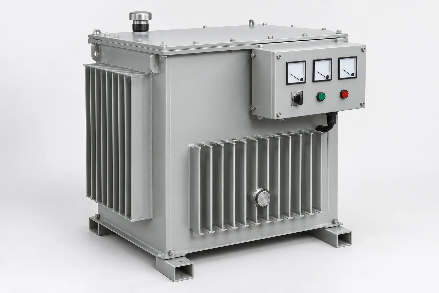
Our ZFLS range lists 323–456 V input and 380 V output. We develop the selected model's operating duty, fluid arrangement, electrical interfaces and installation details around your project.
Explore our 100–3,000 kVA ZFLS range
Compare our 16 ZFLS models using capacity, input and output voltage, dimensions and weight. A capacity shortlist is most useful when it is considered alongside the supply conditions and the physical installation.
Move from a model to your configuration
The model inquiry button keeps the selected model and capacity together. Tell us what equipment it will supply and how that equipment operates; we can then discuss the electrical duty, cooling space and handling arrangement. For an existing installation, the present equipment reference and layout help establish the connections and space the new unit needs to fit.
| Model | Capacity (kVA) | Input voltage | Output voltage | Overall dimensions (mm) | Weight (kg) | Inquiry |
|---|---|---|---|---|---|---|
| ZFLS-100 | 100 | 323-456V | 380V | 700 × 700 × 1350 | 450 | |
| ZFLS-150 | 150 | 323-456V | 380V | 750 × 750 × 1350 | 550 | |
| ZFLS-200 | 200 | 323-456V | 380V | 750 × 750 × 1350 | 750 | |
| ZFLS-250 | 250 | 323-456V | 380V | 750 × 750 × 1350 | 850 | |
| ZFLS-300 | 300 | 323-456V | 380V | 1000 × 1000 × 1700 | 1100 | |
| ZFLS-350 | 350 | 323-456V | 380V | 1000 × 1000 × 1700 | 1150 | |
| ZFLS-400 | 400 | 323-456V | 380V | 1000 × 1000 × 1700 | 1200 | |
| ZFLS-500 | 500 | 323-456V | 380V | 1100 × 1100 × 1700 | 1250 | |
| ZFLS-600 | 600 | 323-456V | 380V | 1200 × 1200 × 1700 | 1400 | |
| ZFLS-800 | 800 | 323-456V | 380V | 1100 × 1100 × 2000 | 1800 | |
| ZFLS-1000 | 1000 | 323-456V | 380V | 1100 × 1100 × 2000 | 1900 | |
| ZFLS-1250 | 1250 | 323-456V | 380V | 1200 × 1200 × 2000 | 2000 | |
| ZFLS-1600 | 1600 | 323-456V | 380V | 1300 × 1300 × 2000 | 2500 | |
| ZFLS-2000 | 2000 | 323-456V | 380V | 1550 × 1550 × 2300 | 4000 | |
| ZFLS-2500 | 2500 | 323-456V | 380V | 1600 × 1600 × 2300 | 5000 | |
| ZFLS-3000 | 3000 | 323-456V | 380V | 1700 × 1700 × 2400 | 6500 |
No matching model. Clear the search or describe your required capacity in an inquiry.
Combine induction regulation with oil cooling
Our ZFLS series uses an induction regulating structure with brushless, contactless voltage adjustment. The regulating mechanism works through magnetic coupling, while the control arrangement responds to the voltage requirement.
Oil immersion provides a heat-transfer path from the active parts toward the tank and its cooling surfaces. The fluid also works with the electrical insulation system, so thermal design and insulation compatibility are considered together.
Choose the structure for the application
We discuss the operating conditions and installation preferences when comparing stabilizer types. Our ZFSBW series provides the separate compensated-stabilizer range for projects evaluating that construction.
Match the input window to your supply
The ZFLS model range specifies 323–456 V input and 380 V output. We use the supply range at the intended connection point to discuss the selected capacity and operating conditions.
The project electrical schedule identifies frequency, phase arrangement and the line or phase voltage basis, together with any neutral requirement. Supply conditions beyond the listed range need a separate configuration discussion; 480 V, for example, is above its upper limit.
On the load side, the equipment's required voltage and permitted variation provide the basis for agreeing regulation performance and the appropriate measurement points.
Connect regulation performance to the load cycle
We consider continuous demand, motor starting, intermittent peaks and phase loading when discussing the model. Low input voltage can increase the current needed to supply the load, so the operating envelope belongs with the capacity selection.
| Application detail | Configuration discussion |
|---|---|
| Steady load and output requirement | Setpoint, tolerance and measurement basis |
| Input or load changes | Change magnitude and required recovery behavior |
| Continuous thermal duty | Ambient conditions and cooling arrangement |
| Peaks or imbalance | Magnitude, duration and protective response |
| Nonlinear equipment | Current waveform and relevant performance requirements |
Coordinate fluid, insulation and seals
The fluid forms part of the selected construction. Its heat-transfer behavior, electrical properties and compatibility with insulation and seals affect how the complete unit performs and is maintained.
Fluid selection and service conditions
Mineral-oil and ester-based fluids have different property and compatibility considerations. Where a project specifies a fluid type, we discuss it as a construction requirement alongside operating temperature, environmental conditions and the associated handling information.
The agreed fluid identity, quantity and fill condition belong in the project documents. Later fluid changes or top-ups follow the selected equipment and fluid instructions so the original material relationships are preserved.
Provide space for cooling and service access
We coordinate the unit's position with ambient temperature, available ventilation and nearby equipment. The tank and cooling surfaces need a suitable path for releasing heat, while controls, terminals and service points need practical access.
Installation exposure also influences the enclosure finish and the protection of external components. Winding insulation and the thermal arrangement are considered with the intended duty.
The site's fluid-containment and fire-protection provisions use the selected fluid information and installation conditions. Bringing those requirements into the layout discussion early helps connect the unit's mechanical envelope to the space it will occupy.
Plan the operating and transport arrangements together
Table dimensions and weight help compare model sizes. The project drawing then identifies dimension directions, mounting points, terminal access and any projecting accessories.
Operating mass and shipped condition
Fluid fill and separately packed components affect the relationship between operating mass, transport mass and packed weight. We coordinate the shipping arrangement with the selected unit so the logistics team can plan from the appropriate figures.
Doorways, the delivery route and the final support structure also influence handling. Lifting provisions and any handling restrictions belong with the agreed mechanical and packing documents.
Coordinate protection and any bypass arrangement
We discuss the required response to out-of-range input, overload, phase loss and thermal or control alarms as part of the electrical configuration. The key question is how the connected equipment should behave when normal regulation is interrupted.
Bypass as a project interface
Where the project includes bypass, its circuit and interlocking need to define the supply path, transfer behavior and the voltage the load will receive. Those decisions belong in the system design together with upstream and downstream protection.
Operating instructions follow the selected arrangement, with switching and electrical work handled by qualified personnel.
Support production with coordinated project documents
Our manufacturing capacity includes 3,000 voltage stabilizers annually. Load-test resources, AC test supplies and temperature monitoring support our work on the operating behavior and thermal requirements of the agreed configuration.
For a ZFLS order, we align the drawing, nameplate details, fluid information and agreed checks with the model being supplied. Packing and receiving information then connect that configuration to delivery.
Keep the cooling and control parts accessible
Maintenance planning covers cooling surfaces, seals, controls and any fluid-condition checks specified for the unit. Recording load conditions, alarms and observations helps the operating team discuss changes with accurate equipment information.
Discuss a ZFLS model for your installation
Start with the model or required capacity, the input supply range and the equipment it will feed. We can then discuss output requirements, frequency, load cycle and installation conditions.
Quantity, destination, available space and transport constraints help complete the project picture. Include a site layout or fluid requirement if available. Our voltage stabilizer range gives further context for the wider system choice.