
Electric Meter Boxes and Metering Enclosures
We build meter-box configurations around your meter, service and mounting requirements. Our approach brings the enclosure, equipment layout and cable interfaces together for a clear installation and an accessible metering arrangement.
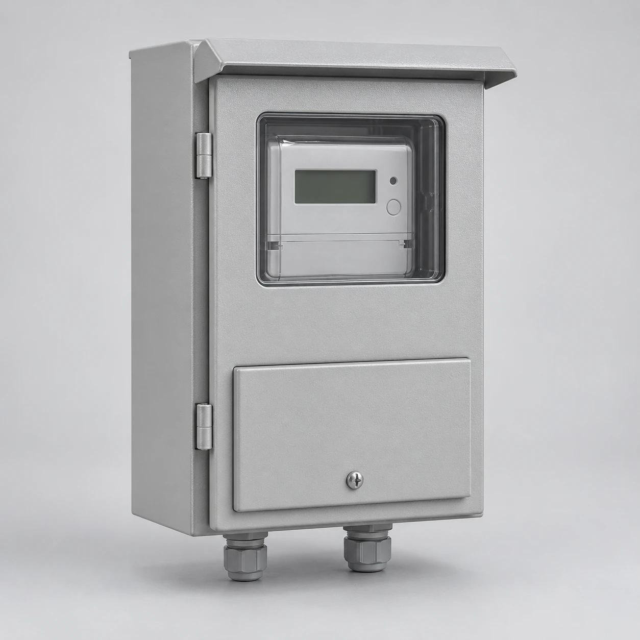
We coordinate the enclosure, mounting board and selected accessories as part of your project. The meter, socket, instrument transformers and protective equipment each have a defined place in the agreed supply scope.
Our meter-box configurations start with the application
We organize a meter-box project around the service arrangement, number of accounts, metering method and installation location. These choices work together: a multi-account building, for example, also needs a mounting format and a layout suited to its selected meters.
| Application need | Configuration focus | Explore |
|---|---|---|
| Service arrangement | Meter interface, terminals and conductor layout | Single-phase / three-phase meter boxes |
| Instrument-transformer metering | Instrument space and measurement interfaces | CT metering cabinets |
| Metering with a main device | Meter, main and outgoing sections | Meter-main panels |
| Multiple accounts | Meter positions and outgoing destinations | Multi-meter enclosures |
| External exposure | Doors, seals, entries and surface protection | Outdoor meter boxes |
| Building interface | Projection, wall opening and access | Surface-mounted / recessed boxes |
| Connected metering | Meter, user interface and communication hardware | Prepaid and smart-meter enclosures |
| Temporary site supply | Metering, outlets and site support | Temporary meter panels |
| Existing equipment | Part fit and replacement interfaces | Doors and parts / maintenance and replacement |
We coordinate the enclosure and the equipment it houses
The box protects and supports the metering equipment; the meter measures energy use. We use these distinct functions to organize usable space, access and the connections between components.
| Component | Role in the configuration |
|---|---|
| Enclosure and mounting board | Mechanical housing, fixing area and access |
| Meter socket or mounting kit | Interface to the selected meter |
| Revenue meter | Measurement equipment from the assigned authorized provider |
| CTs and sensing equipment | Measurement interfaces in transformer-operated arrangements |
| Main and protective devices | Specified disconnection and circuit-protection functions |
| Terminals and internal connections | Connections within the agreed assembly boundary |
We establish the components included in our scope alongside equipment provided by the utility or project team. That keeps the physical layout and supply arrangement consistent.
Our service layout follows the project connection requirements
We work from the service arrangement for the actual installation: voltage, frequency, phase, conductors and incoming cable route. The serving utility's project drawing gives the metering interface and the relevant ownership and access boundaries.
We bring these inputs into the enclosure layout so the incoming connection, meter position and downstream cable route can be considered together. Where the service arrangement is still being developed, we start with the installation location and intended use, then refine the drawing as the project information becomes available.
Match each rating to the component it describes
We treat a requested ampere rating as a project input and identify the part of the service it belongs to. Our quotation aligns the enclosure, meter interface and fitted equipment with the specified service arrangement.
| Component or boundary | Field to define for the project | What the field describes |
|---|---|---|
| Empty enclosure | Dimensions, material, mounting, entries and environmental construction | Housing and installation space; enclosure dimensions do not establish a service-current rating |
| Meter socket or CT interface | Specified socket form and rating, or CT ratio, secondary interface and mounting | The selected measurement connection; direct and CT arrangements use different interfaces |
| Energy meter | Meter model, voltage and current-input arrangement | The measurement device and the service or instrument-transformer signal it accepts |
| Main device, busbars and terminals | Specified device duty, continuous-current conditions and conductor interfaces | The configured power path and its individual components |
| Complete fitted assembly | Applicable assembly ratings, fault duty and operating conditions | The complete construction, rather than the highest rating of one component |
| Utility service interface | Project drawing, service configuration, access and sealing requirements | The connection arrangement for the serving utility and installation |
We align the meter interface with the mounting layout
We coordinate the selected meter's body envelope, fixing pattern, contact arrangement and terminal space. For socket-mounted meters, the socket form and contact layout establish the electrical interface; for board-mounted meters, the fixing centres and terminal-cover space shape the mounting area.
Ring or ringless retention and any specified bypass arrangement are handled as individual project choices. We also consider meter visibility, cover movement and sealing areas. Bringing these details onto the same layout helps the meter fit and function within the finished enclosure.
Direct and CT metering shape the internal arrangement
Direct-connected metering places the meter interface in the service-current path. A transformer-operated arrangement uses instrument transformers and separate measurement connections, adding requirements for device space, measurement terminals and the specified test facilities.
We use the project's metering method to organize these areas within the cabinet. CT selection follows the service and utility arrangement rather than a single current threshold. Our CT metering cabinets discussion connects the instrument layout with the metering compartment and adjacent electrical equipment.
We organize meter positions around the accounts served
Phase describes the electrical service; meter-position count describes the separately metered supplies. We keep these dimensions separate when discussing a single account, a multi-tenant building or a project with future positions.
For multiple accounts, the position schedule connects each meter to its premises or outgoing destination. We coordinate the common incoming area, individual connections and identification so the arrangement remains understandable during use. Future provision can mean reserved space or an equipped position; the selected approach also needs the corresponding electrical capacity.
Mounting and cable access work as one design
We consider the wall or support, cable approach and nearby equipment when developing the enclosure arrangement. Surface mounting introduces projection and fixing requirements; recessed mounting connects the enclosure to a wall opening and finished surface. A freestanding arrangement adds its own support interface.
Our layout discussion distinguishes outside dimensions, usable internal space and the access needed by doors and covers. Cable bend space and terminal reach are considered alongside meter placement. This helps the project team coordinate the box with the surrounding building before installation.
We compare materials against the installation environment
Metal construction
Metal panels provide mechanical support for doors, mounting boards and fitted components. We consider panel structure, surface finish and corrosion exposure together, with bonding provisions coordinated in the electrical design.
Non-metallic construction
Non-metallic materials offer electrically insulating enclosure structures and can reduce weight. Material selection still depends on impact, sunlight, temperature and the installation's fire-performance requirements.
We treat the door, viewing window, gasket and cable entries as parts of the complete enclosure. The mounting board supports the equipment layout, while terminal selection follows the conductor material, size range and connection requirements. The chosen construction is defined for the project.
Our project documents connect dimensions and components
We coordinate the general arrangement, meter interface, component scope and identification with your project requirements. The same drawing reference connects the mounting pattern, entry positions and equipment arrangement, making configuration discussions more precise.
Our manufacturing and quality checks follow the selected equipment and agreed inspection scope. We discuss relevant dimensional, assembly and functional checks together with the documents needed for the installation. Utility coordination remains part of the service design, alongside our equipment drawings.
We coordinate delivery and ongoing equipment identification
We discuss packing and delivery around the enclosure size, fitted components and site access. Package identification and the component schedule help the receiving team connect the delivery to the order and identify doors, mounting parts and other supplied accessories.
For later parts or configuration questions, the model, drawing reference and accessible identification help us understand the installed arrangement. Meter handling and sealed sections stay with the authorized utility parties; electrical installation and internal service belong to qualified personnel. Normal observations focus on accessible displays and external condition.
Tell us about your metering project
How we develop your meter-box quotation
We base the quotation on the enclosure material and dimensions, number of meter positions, mounting arrangement and included components, such as a socket, terminals or main device. Quantity, destination and the agreed packing and delivery scope complete the commercial brief. Our multi-meter layouts, CT metering configurations and meter-main arrangements explain how those choices change the equipment scope.
Start with the service arrangement, number of meter positions and installation location. Add the meter reference, mounting preference and quantity if known. We can then discuss the enclosure layout and component scope with your team.
Utility drawings, cable routes and project documentation can follow as the configuration develops. Whether you need a new enclosure, a coordinated metering assembly or help identifying a replacement interface, we welcome your project details.