
Recessed Meter Boxes
We coordinate recessed meter boxes with the wall, meter arrangement and cable space. Bringing the enclosure body into the wall can reduce exposed projection, while a carefully positioned frame and door give the installation a clear, integrated appearance.
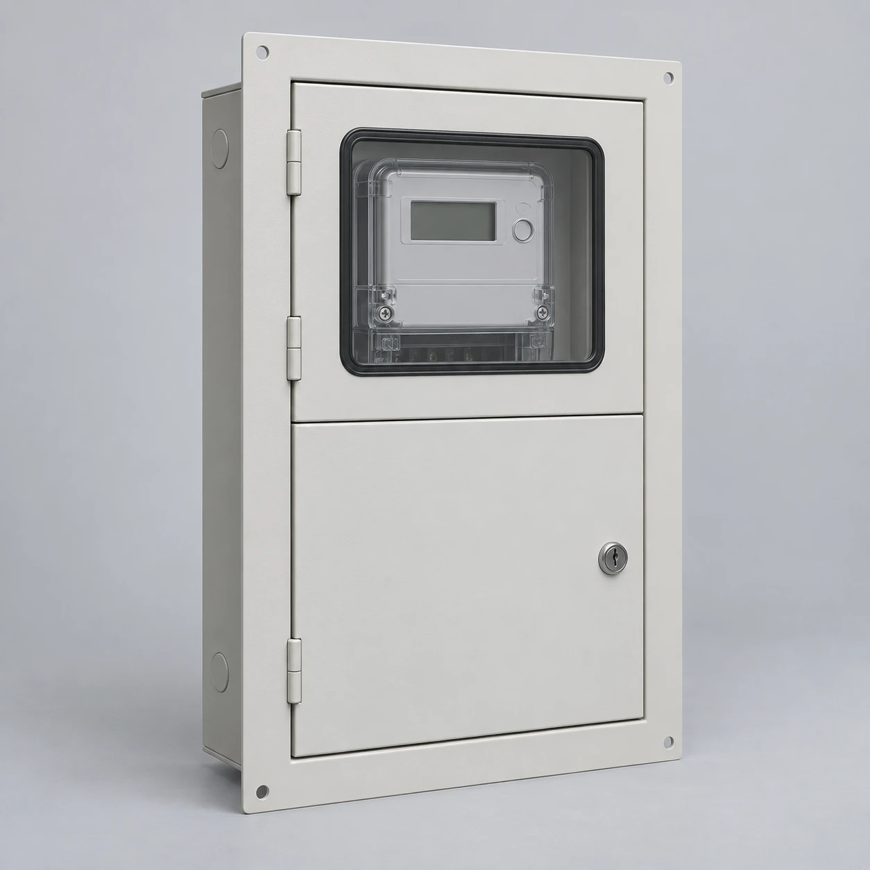
Our project layout connects enclosure dimensions, meter interfaces and finished-wall details. The mounting arrangement is developed with the building and electrical requirements, including the applicable utility access provisions.
Integrate the meter enclosure with the wall
A recessed arrangement places part or all of the enclosure body within the wall opening. We discuss the desired appearance alongside the meter depth, cable approach and available wall construction. These details determine how much of the body, frame and door remains visible.
Choose the mounting relationship
The building layout and utility access requirements help determine whether a recess suits the installation. A surface-mounted meter box uses a different relationship to the wall and may fit other project conditions. For a recessed configuration, we coordinate the opening and frame together so the enclosure and finished surface meet as intended.
Define the profile from body to finished surface
Recessed, flush, inset and semi-recessed describe different degrees of wall integration. The useful detail is the position of the enclosure body, frame and door relative to the finished wall plane. We establish that relationship through the project section and elevation views.
Allow for the metering equipment
Meter form, position count, service arrangement and conductor routes determine the internal space. Backboards, mounting hardware and terminal access also occupy depth. An enclosure, a fitted metering assembly and a replacement door or frame therefore begin with different interface needs, even when the visible opening appears similar.
Distinguish the opening, body, frame and usable depth
The wall opening accommodates the enclosure and installation allowances. The body's external dimensions describe the shell itself. The frame or flange overlaps the wall face, while usable internal depth is the space left for equipment and cables within the fitted construction.
We keep these dimensions separate in the layout. A body that fits the opening still needs suitable frame overlap, and an adequate external depth still needs enough usable space after the mounting plate and meter are included.
Use the finished wall as a common reference
We connect the enclosure dimensions to clearly identified reference points. Consistent mm or inch units and a shared finished-wall plane help the cabinet, frame and building detail fit together.
| Dimension group | Details to coordinate | Reference |
|---|---|---|
| Wall opening | Width, height and available depth | Structural or finished opening |
| Enclosure body | External width, height and depth | Body outline |
| Frame or flange | Overall size, overlap and fixing positions | Finished wall plane |
| Usable space | Clear opening and internal depth | Fitted mounting and meter arrangement |
| Door and access | Projection and movement envelope | Wall returns and adjacent objects |
Coordinate the wall build-up and enclosure perimeter
Wall finish thickness changes where the frame sits and how much overlap is visible. Cladding, render or other finishes can also affect fixing access and the edge around the opening. We discuss these relationships with the project team alongside the supporting arrangement.
Connect enclosure and building details
Structure, insulation, fire performance and weather control are coordinated through the project's building detail. For an external wall, flashing and perimeter treatment work with the enclosure's own closure and entry arrangement. Our outdoor meter boxes page explains the environmental considerations that remain relevant when a box is recessed.
Reserve space for cables and door movement
We consider the cable route from entry to terminal alongside the meter and its mounting equipment. Cable bends, supports and connection access can use space beyond the meter's outline. A rear or bottom entry may therefore lead to a different internal layout.
Keep access usable after finishing
The frame, hinges and latch must work with wall returns, cladding and nearby equipment. Door swing and meter visibility need attention before the final face position is settled. Coordinating these details helps prevent a fitted meter or cable route from occupying the space needed to open, read or service the assembly.
Match frame construction and finish to the installation
Frame rigidity helps maintain the intended opening and door alignment. Body and frame materials, reinforcement and fixing positions work together with the mounting load. We discuss surface treatment around edges, fasteners and the interface with the wall finish.
Coordinate the closure components
Hinges determine the movement path, latches hold the door in position and seals close the intended perimeter. Their geometry must match the retained or proposed frame. The project drawing brings material requirements, dimensions, tolerances and finished-wall references together so fabrication and building coordination use the same arrangement.
Choose the right starting point for new or existing work
New installation
We coordinate the enclosure outline, frame and intended opening as the wall detail develops. Meter depth and cable routes are incorporated before the body and frame relationship is settled.
Complete replacement
The existing opening, finish and accessible external dimensions establish the starting envelope. The replacement arrangement also needs to suit the metering equipment and incoming cables.
Door or frame matching
When the body remains, the fixing positions, hinge geometry, latch and seal interfaces become central. Our meter-box parts page covers this identification process. Internal measurements and electrical work are carried out by authorized personnel.
Protect the frame and retain useful part references
Project delivery planning includes protection for projecting frame corners, doors, hinges and finished surfaces. These parts need to arrive with their alignment and mating features intact. Clear part identification helps connect separately packed items with the assembly drawing.
Support future configuration discussions
The final body, frame, hinge, latch and gasket references provide a basis for later maintenance or replacement selection. A similar overall outline does not establish that every fixing and closure detail matches. Keeping the finished-wall detail with those references is particularly useful when the enclosure remains in place through a building refurbishment.
Discuss your recessed meter box with us
Tell us whether the project is a new installation, a complete replacement or a door/frame requirement. Share the available external dimensions, meter arrangement, wall location and quantity. We can then focus the discussion on the interfaces that shape that particular configuration.
Wall sections, existing drawings and exterior photographs can be exchanged as the project develops. We bring the opening, body, frame and usable-space dimensions together with cable entry and access requirements, giving the enclosure and building teams a common layout to work from.