
Single-Phase Meter Boxes
We configure single-phase meter boxes around the selected meter, its mounting interface and the installation space. For new projects and replacement enquiries, we bring the enclosure, reading access and cable routes into one coordinated layout.
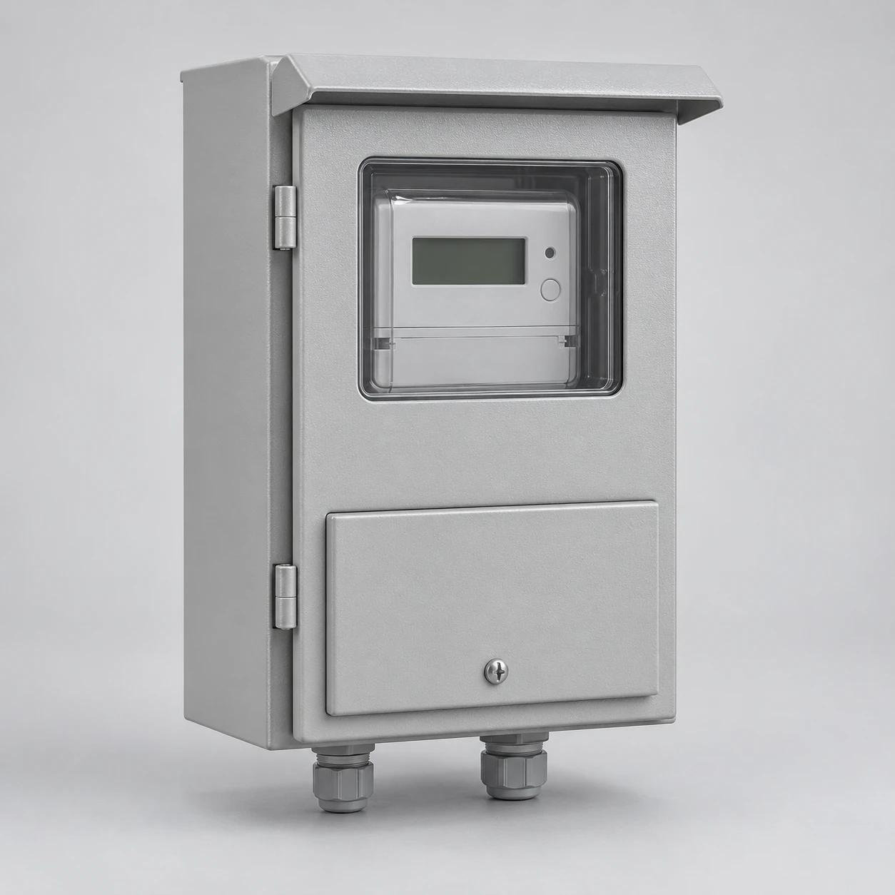
Our project discussion connects the box, mounting board or socket, terminals and any adjacent main equipment. We agree the included components with your team and the assigned meter provider.
We match the box to the single-phase service
We consider voltage, frequency, conductor arrangement and required current as separate design inputs. Together, they establish the service interface around which the meter and its connections are arranged. The number of meter positions is another choice, linked to the accounts served.
A service requirement example
A project brief might specify 120/240 V, single-phase, three-wire, 60 Hz. We pair that service description with the project's selected meter and utility drawing to develop the layout. The example describes a project input; the equipment configuration follows the actual installation requirements.
Our mounting layout follows the meter interface
We coordinate socket-mounted meters around the specified socket form, contact arrangement and retention details. Ring or ringless construction and any required bypass belong to that particular service arrangement. Meter dimensions, socket depth and terminal space are considered together.
For a board-mounted meter, fixing centres and terminal-cover clearance define its position on the mounting board. We also consider the display location and access to the surrounding covers. These details connect the electrical interface to the practical arrangement inside the box, using the selected meter drawing as the reference.
DIN-rail meters and the purpose of measurement
For a selected DIN-rail meter, we coordinate the specified rail or fixing interface, device width, terminal-cover movement and surrounding wiring space. We also establish whether the device serves utility revenue metering or a project submetering function. The mounting style alone does not determine that role: the meter reference, service arrangement and responsible provider define the application. We use those details to develop the box layout around the selected equipment.
We organize the enclosure and its associated components
We use a component schedule to connect the physical layout to the supply scope. It identifies the enclosure and mounting provisions alongside any selected socket, terminals or main equipment.
| Configuration area | Function | Our coordination focus |
|---|---|---|
| Enclosure and door | Housing, protection and access | Dimensions, mounting and closure |
| Board or socket support | Location of the selected meter | Fixing pattern, clearance and interface |
| Metering equipment | Measurement for the assigned account | Device reference and authorized provider |
| Terminals and connections | Incoming and outgoing electrical interfaces | Conductor compatibility and cable space |
| Main or protective equipment | Specified switching and protection | Device area and adjacent assembly boundary |
When a main device shares the assembly, our meter-main combinations content explains the additional layout relationships.
Single-phase service and meter-position count are separate choices
A single-phase service may serve one account or be part of a building with several separately metered accounts. We organize the meter positions around those accounts and their outgoing destinations, keeping the electrical service description distinct from the position count.
For a shared assembly, the common incoming area, individual connection routes and permanent identification all need space. Our multi-meter enclosures discussion develops that arrangement. When future positions are part of the project, we distinguish reserved physical space from equipped positions and the capacity needed to use them.
We coordinate usable board and termination space
Our layout separates the outside envelope from the space actually available for equipment. The meter footprint, its fixings, the terminal zone and the door's internal clearance all affect the usable mounting area.
We consider conductor material and size range alongside the selected terminal arrangement. Cable bends and entry positions then connect that terminal zone to the installation route. This approach keeps the meter and connections accessible within the finished enclosure, rather than using the outside box dimensions as the only measure of fit.
Reading and service access are part of our layout
We position the meter with its display and intended reading method in mind. Where a viewing window is part of the design, its location follows the display rather than a generic opening. Door movement and removable-cover space are considered at the same time.
We coordinate customer-accessible areas and utility sealing zones with the project arrangement. Clear separation helps ordinary reading and observation remain straightforward while the protected connections retain their designated access. Meter handling, seals and internal electrical work stay with the authorized utility parties and qualified personnel.
We bring mounting and cable routes together
We discuss the support surface, available footprint and incoming service route before settling the enclosure geometry. An overhead or underground approach can change the entry area, while the downstream route shapes the terminal and cable space.
With surface mounting, we consider projection, fixings and door access. A recessed arrangement connects the enclosure to the wall opening and finished surface. For freestanding projects, the support interface becomes part of the same discussion. Nearby equipment and building features complete the installation picture.
We discuss materials around exposure and use
Metal enclosure choices
Metal construction provides mechanical support for the door, mounting board and fitted equipment. The selected finish addresses the exposure conditions, while bonding provisions are coordinated with the electrical arrangement.
Non-metallic enclosure choices
Non-metallic construction provides an insulating structure and can reduce weight. Impact, sunlight, temperature and fire-performance requirements guide the material choice for its intended location.
We consider the viewing window, seals, hinges, mounting board and entry fittings as parts of the complete box. Their fit and placement influence everyday reading, closure and the enclosure's performance in service.
We follow different paths for new and replacement projects
New installations
We coordinate the proposed location, wall or support interface, meter layout and incoming cable route. Early dimension and access discussions help align the enclosure with the building work and service arrangement.
Replacement projects
We begin with the existing identification and available drawings or exterior photographs. The comparison covers overall dimensions, fixing points, entries, door or cover fit and sealing interfaces. A change in size or location may also affect surrounding building work and service coordination.
We can start the discussion from safely accessible information, with any concealed details handled through the project team's authorized survey.
Our delivery information supports receiving and later parts enquiries
We connect the equipment reference, final layout and supplied-component information so the receiving team can identify the enclosure and its accessories. Packing discussions consider the door, window, mounting provisions and loose components, together with the transport route.
For a later door, cover or hardware enquiry, the original part or drawing reference helps us compare the mating features and installed configuration. Our doors and accessories page develops those details, while our replacement and maintenance information connects the equipment question with the appropriate project route.
Talk with us about your single-phase meter box
Tell us whether the project is a new installation or a replacement. For new equipment, start with the service arrangement, meter reference, mounting location and quantity. For an existing box, the accessible maker or model reference and exterior dimensions help us begin the fit discussion.
We can then work through cable routes, included components and the relevant utility drawing with your team. Your first enquiry can focus on the information already available and the layout questions you want to resolve.