
Meter Box Selection, Replacement and Care
In this guide, we explain how to approach a new meter enclosure, replacement part, complete box replacement or change of location. We help you connect the equipment requirement to the meter, mounting and cable interfaces that shape the project.
Our selection discussion focuses on enclosures, parts and their physical interfaces. We coordinate those requirements with your project team, while the utility and qualified installer handle their assigned metering and electrical work.
We start by identifying the equipment involved
The meter measures energy use, the enclosure houses or supports it, and a socket provides the selected meter interface. Main protection and disconnection perform their separate electrical functions. We use these distinctions to understand whether the enquiry concerns the housing, a mechanical part or another area of the installation.
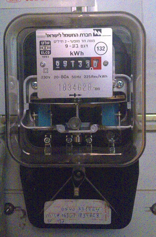
Our meter-box range connects those functions to the available configuration discussions. The meter's display, the door and the surrounding enclosure may be visible together, but each provides different information about the installed arrangement.

Our selection discussion follows four project routes
The intended work determines which interfaces we discuss first. These routes connect a practical equipment need to the information that helps develop the proposal.
| Project route | Our interface focus | Related equipment |
|---|---|---|
| New installation | Service, meter and mounting layout | Meter enclosures |
| Door or mechanical part | Existing model and mating features | Doors, frames and accessories |
| Complete enclosure replacement | Old/new footprint, entries and access | Selected enclosure configuration |
| Relocation | Proposed position, support and cable routes | Enclosure and mounting arrangement |
We can begin with the information already available, then develop the remaining equipment details with your team.
We connect a new enclosure to the service and location
For a new project, we discuss voltage, phase, conductors, frequency and the selected meter interface together with the number of accounts. Direct and transformer-operated metering create different equipment and compartment requirements; our CT metering cabinets content develops the instrument arrangement.
We then bring the mounting format, cable approach, available space and exposure into the enclosure layout. A main device or distribution section adds its own component and access requirements. The resulting discussion connects the service drawing to the physical box and the equipment included in the project.
Existing identification gives us a useful starting point
A visible maker or model label, an original drawing or a purchase record can identify the enclosure variant. Exterior photographs show the front, surrounding wall and visible condition, while clearly named dimensions distinguish the complete box from a door or frame.
We use safely accessible exterior information with meters, seals and protected covers left in place. Concealed details are handled through the utility or a qualified assessor's authorized survey. Our parts-matching page explains the measurement references for hinge centres, latch position, opening dimensions and edge overlap.
We compare the part with the structure around it
Door and frame interfaces
A door's overall size is only one matching feature. Hinge handing and centre spacing, pin geometry, latch engagement, edge overlap and the seal profile connect it to the existing frame. We discuss those features together with the condition of the retained structure.
Complete enclosure interfaces
A change to the box body brings mounting points, cable entries and equipment positions into the comparison. We consider the proposed enclosure depth, door clearance and surrounding building features with your team. The selected material and finish also need to suit the installation's exposure and mechanical duty.
External care helps keep condition information useful
Normal external observations can identify door-closure problems, surface corrosion, damaged seals and fading identification. The equipment instructions and site conditions guide observation and care intervals. We use clear descriptions and accessible photographs to understand the relevant enclosure or part question.
| Note | Practical use |
|---|---|
| Date and visible identifier | Connect the observation to the equipment |
| External condition | Describe the door, finish, seal or label |
| Photo or drawing reference | Locate the affected feature |
| Previous part or repair reference | Understand the installed configuration |
A note such as “the door does not close fully” is more useful than guessing which hinge or support has caused the change.
Electrical abnormalities need a professional response
Water entering electrical equipment, sparking, burning smells or exposed damaged conductors call for keeping clear and contacting the utility or local qualified emergency service. Do not touch, open or attempt to dry the equipment; use local emergency services for immediate danger.
Repeated tripping should be assessed by a qualified electrician. Increasing a breaker or fuse rating is not a remedy. We keep the enclosure and parts discussion focused on the equipment requirement once the responsible professionals have identified the work needed.
We compare the old and proposed installation interfaces
For replacement, we compare the box dimensions, fixing pattern, meter position, entries and door area. These details show how the proposed equipment meets the existing support and cable routes.
For relocation, the new position adds support, access and route changes to the discussion. We coordinate our enclosure information with your team's site plan, while the utility and installer arrange their metering, connection and inspection work. Building repairs or changes to surrounding surfaces can also affect the final opening and mounting details. The selected layout gives these activities a common equipment reference.
Our equipment proposal connects parts, documents and delivery
We identify the enclosure or parts, agreed configuration information and packing scope in the equipment discussion. Drawings, component references and any selected accessories help make the proposed supply clear.
A replacement or relocation project's total cost can also include utility, electrical and building work. We coordinate the equipment interfaces with those assigned activities rather than treating the box price as the complete project. For delivery, package identification and the parts list help the receiving team recognize the supplied items. The final equipment references also support later questions about fit or configuration.
Talk with us about the enclosure or part you need
Tell us which route fits your project: new enclosure, mechanical part, complete replacement or relocation. For a new box, start with the service, meter and mounting location. For existing equipment, begin with the accessible identification, required part and visible condition.
Add quantity and mention any drawings or exterior photographs available for a follow-up exchange. We can then discuss the equipment configuration and the interfaces that need attention with your project team.