
Industrial AC Voltage Stabilizers
Our industrial AC voltage stabilizers help match changing supply conditions to the voltage requirements of production equipment. We configure the regulation requirement around the input range, connected load and operating cycle, with our ZFSBW compensated and ZFLS oil-immersed series offering starting points for the project.
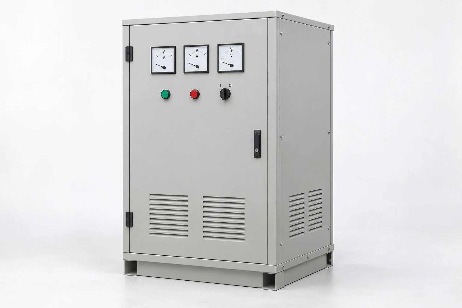
Address voltage variation at the equipment supply
We begin with the production problem: supply voltage moving outside a machine's permitted range, changing conditions across a work shift or a demanding load entering service. The relationship between these events and the affected equipment guides the regulation requirement.
A stabilizer adjusts voltage within its configured operating range. A fixed-ratio transformer provides a different voltage relationship, while an AC frequency converter addresses frequency requirements. Stabilization retains the supply frequency. Where a project also needs backup power or electrical isolation, we coordinate those as separate functions in the power arrangement.
Use the supply pattern to shape the configuration
Magnitude, duration and load state
Minimum and maximum voltage establish the initial range, but timing explains the problem. A sustained low-voltage condition and a brief event during motor starting can affect the same machine differently. We use the available records to connect voltage behavior to the operating cycle.
| Information | What it clarifies |
|---|---|
| Minimum and maximum voltage | Required input operating window |
| Event depth and duration | Sustained variation versus brief disturbance |
| Individual phase behavior | Three-phase balance and control needs |
| Machine and switching sequence | Repeatable conditions for the configuration |
Where records are needed, the site's qualified team can gather them at the relevant supply point.
Link the required output to the actual loads
We discuss the equipment's permitted voltage range and the loads the stabilizer will serve. Continuous current or kVA, startup demand, power factor and electronic loads all help describe the duty. The sequence shows which demands occur together.
A machine group can also be divided into the equipment that needs regulated power and other loads served separately. This makes the project boundary useful for both capacity and layout. We include planned additions explicitly, so future demand has a defined basis rather than an unspecified allowance. Output tolerance, phase arrangement and any neutral requirement are then connected to that selected load group.
Separate steady regulation from response and recovery
What happens during a change
Steady output tolerance describes the voltage after conditions settle. Response concerns how regulation reacts to a change, while recovery describes the return to the required band. Both depend on the event being considered, including input variation or a load step.
We discuss the depth, duration and repetition of important events alongside the equipment's tolerance. For a production machine with repeated starts, that discussion connects the operating cycle to the required voltage behavior. It also gives any agreed dynamic checks a clear basis: the starting condition, imposed change and acceptable output response.
Our compensated and oil-immersed stabilizer series
Compensated regulation adjusts a corrective voltage to address supply variation. Oil immersion describes insulation and heat-transfer construction. These are different design dimensions, rather than mutually exclusive categories. Our ZFLS oil-immersed series uses an induction voltage-regulation approach.
| Series | Product configuration | Model information |
|---|---|---|
| ZFSBW | Compensated stabilizer | 14 model entries; 380 V designation |
| ZFLS | Oil-immersed stabilizer | 16 model entries; 323–456 V input and 380 V output |
The ZFSBW 380 V designation alone does not define its input window. We establish the selected model's frequency, input range and regulation requirement in the project configuration; the series pages provide the capacity, dimension and weight comparisons.
Separate regulating architecture from cooling construction
We distinguish electromechanical regulation, which uses a moving regulating mechanism, from static regulation using electronic power switching. This describes how adjustment is made. Compensation describes the corrective-voltage function, while oil immersion describes insulation and heat transfer; those labels alone do not specify the response to a disturbance.
We compare the selected configuration with the depth, speed and frequency of the input events, the required return to tolerance and the available maintenance access. A contactless or static description is therefore only one input to the discussion. We agree the operating response and care requirements for the actual equipment configuration rather than applying one speed or output-accuracy figure across our series.
Consider available output at the lowest input
When a stabilizer supports the load at a lower input voltage, the input-current demand becomes an important part of the power-path assessment. The useful operating envelope therefore connects input voltage, output demand and thermal conditions, rather than relying on one nominal kVA value.
We compare the intended continuous and starting loads with the selected configuration at the demanding input conditions. Any capacity adjustment belongs in that discussion. The project electrical designer then coordinates the feeder and protection with the equipment's operating requirements. This connects voltage correction to the available upstream supply instead of treating regulation as independent of it.
Define the load's supply in each operating state
Normal operation, abnormal input and bypass
We discuss how the project should respond to input outside the operating range, supply loss, overload and internal faults. The intended alarm, output and restoration behavior guides the selected control and protection arrangement.
Where a bypass is part of the configuration, its path and status indication need to be clear. A direct-input bypass passes incoming voltage to the load, so the equipment's tolerance still matters in that state. Restoration of the power supply also needs coordination with machine restart controls. These operating-state decisions become part of the project documentation and professional commissioning procedure.
Coordinate materials, cooling and service access
Core, conductor and insulation choices influence losses, temperature and the physical arrangement. Winding resistance contributes heating; the cooling path carries that heat away. We consider the enclosure environment, ventilation and access alongside the electrical duty.
Oil-immersed construction
Insulating fluid helps transfer heat from internal components to the cooling surfaces while contributing to electrical insulation. Fluid identification, containment arrangements and inspection access therefore belong in installation planning. We discuss the selected construction's care information and service access with the project team, including space around connections and cooling surfaces. Maintenance requirements follow the actual equipment arrangement and operating environment.
Our stabilizer production and project documents
Our annual production capacity is 3,000 voltage stabilizers. Wire and foil winding, vacuum pressure impregnation and high-temperature ovens support our power-equipment manufacturing. Load equipment, AC test supplies and temperature monitoring support the technical work around electrical and thermal requirements.
We align the selected configuration with its outline, terminal and control information, nameplate and agreed inspection plan. Regulation checks can then reference the specified input conditions and loads. Packing, handling and operating information support receiving and installation, while equipment identifiers connect the delivered unit to the project documents and later maintenance discussion.
Discuss your voltage stabilizer
Tell us about the voltage problem, the affected equipment and the required supply. Available input readings and a load list are helpful, but a description of the operating problem is enough to start the discussion. We can organize the remaining configuration inputs with your team.
Add the phase arrangement, frequency, environment and installation space as they become available. Mention important starting events, planned load additions and any bypass requirement. We use this information to discuss a stabilizer configuration that addresses the equipment's duty and the practical conditions at the site.