
Isolation Transformers
We offer single-phase and three-phase isolation transformers for industrial voltage matching and electrical separation. We combine load requirements, winding construction and installation conditions to develop the configuration, from a machine-mounted transformer to a unit integrated into a power cabinet.
Electrical separation through independent windings
Our isolation transformers transfer energy through a magnetic core between electrically separate primary and secondary windings. The turns relationship establishes the voltage relationship, allowing the transformer to match a supply to equipment while maintaining separation between the winding circuits.
Isolation within the complete power system
This separation serves a different purpose from automatic voltage regulation. The transformer retains the supply frequency, and grounding and protective devices remain part of the system design. Isolation alone does not eliminate every noise path or electric-shock risk. Where interference is a concern, we discuss the disturbance and any shielding requirement alongside the electrical configuration.
Single-phase and three-phase configurations
We organize the transformer around the supply and the equipment it powers. Single-phase requirements involve the load voltage, current and duty; three-phase requirements also bring winding connection, phase loading and any neutral requirement into the selection. Clear line-to-line and line-to-neutral references prevent ambiguity in the voltage schedule.
For mixed machine loads, we consider how single-phase auxiliaries are distributed across the phases. A balanced three-phase load and an uneven group of auxiliaries can impose different winding demands. Our ZFSG three-phase series provides a model range for the initial capacity and physical-layout discussion.
Build the electrical configuration around the installation
| Project information | Configuration focus |
|---|---|
| Source and equipment voltages | Primary/secondary relationship and operating variation |
| Supply frequency | Core and winding design for the stated operating frequency |
| Phases, wires and neutral | Winding arrangement and terminal identification |
| Continuous and starting loads | Capacity, voltage behavior and thermal duty |
| Cabinet or room installation | Mounting, cooling and connection access |
We bring these items together in the project configuration so the electrical schedule and mechanical layout describe the same equipment. Frequency is specified for each project rather than assumed from its destination alone.
Capacity that reflects how the load operates
Running demand and simultaneous starts
We consider the operating sequence as well as the connected load. Several motors starting together can create a different voltage demand from the same motors starting separately. Continuous current, power factor and starting behavior therefore belong in the capacity discussion; kilowatts alone do not fully describe transformer loading.
Nonlinear and uneven loads
Rectifier inputs and other nonlinear equipment can change current waveform and heating. Uneven phase loading also affects how capacity is used. We work from the equipment data and duty pattern to address these conditions. Our industrial transformer integration page connects these electrical decisions to machine and cabinet interfaces.
Core, conductor and insulation choices
The core provides the magnetic path, while the winding conductor carries load current. Core design influences magnetic behavior and no-load loss; winding dimensions and resistance influence load-related heating. We discuss these together because changing one material does not define the performance of the complete transformer.
Copper and aluminum in a complete design
Copper and aluminum require different conductor cross-sections and termination arrangements for a given design. Space, mass, connection compatibility and thermal behavior guide the comparison. The insulation system separates conductors and withstands operating stress; its thermal classification works alongside temperature rise, ambient conditions and cooling. An electrostatic screen is a separate configuration discussion where the interference requirement calls for it.
Fit the transformer into the power cabinet
We coordinate the transformer outline, mounting points, terminal approach and heat rejection with the surrounding assembly. Cable bending space and access for inspection matter as much as the footprint. In an enclosed cabinet, transformer losses join the heat from switches, power supplies and other equipment.
The project electrical designer coordinates grounding, secondary circuits and protection with the source characteristics. Transformer impedance and energization behavior inform that work. We keep these interfaces visible in the configuration discussion, helping the cabinet team reserve practical ventilation paths and service space without treating an outline drawing as the whole installation design.
Our ZFSG three-phase isolation transformer series
Our ZFSG three-phase series includes 21 models from 5 to 500 kVA. The ZFSG series table brings together model, capacity, voltage, enclosure dimensions and weight for initial selection. We then develop the selected voltage arrangement, operating frequency and installation details around the project.
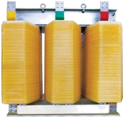
The model range makes it easier to compare capacity and physical space while keeping connection and duty decisions tied to the actual application.
Match the power function to the application
| Application need | Product function |
|---|---|
| Voltage matching with separate windings | Isolation transformer |
| Shared-winding voltage conversion | Autotransformer |
| Correction of supply-voltage variation | Voltage stabilizer |
| Controlled AC output frequency | AC frequency converter |
Where a project combines these functions, we discuss the sequence and interfaces so each device has a clear role in the power path.
Our transformer production and project documents
Our manufacturing capabilities include wire and foil winding, vacuum pressure impregnation and high-temperature ovens. Winding controls conductor placement; impregnation and drying support the insulation construction. These processes connect the electrical design to the finished assembly.
Core-loss and interturn testing, a high-current load platform, AC test supplies and temperature monitoring support our production and technical work. We align the agreed inspection items with the selected configuration. Project documents bring together the nameplate information, connection and terminal details, outline drawing and agreed test records so the receiving and integration teams can identify the equipment consistently.
Start with your source and load
Tell us the available supply, required load voltage, approximate capacity and application. Equipment nameplates or a load list help us develop the next questions about frequency, starting duty, neutral arrangements and installation conditions. We can refine the configuration with your machine or cabinet team as the project develops.
We also discuss packing dimensions, handling information and the drawings needed for integration. Qualified personnel install and commission the transformer using the project documents. Keeping cooling paths accessible and equipment identifiers available supports later inspection and maintenance planning.