
Building Power Outlet and Switch Interfaces
We help align specified outlets and switches with the boxes, mounting details and power connections around them. Our project discussion brings together the connected load, exact device interface and installation space so the electrical and mechanical details work together.
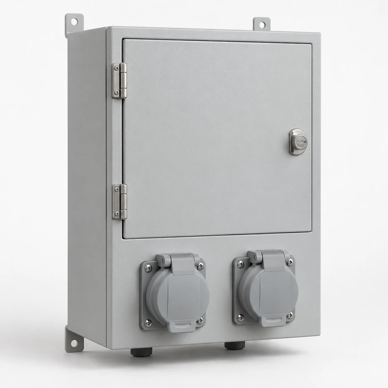
Connect the building task to our equipment interfaces
Our starting point is the equipment connection and its location: a wall outlet for an appliance, a switched lighting circuit, or a power interface built into a specified installation. We use that context to discuss the box arrangement, mounting surface and connection to the project's distribution equipment.
Power connection and user control
A receptacle provides the equipment connection; a switch defines an operating action. Where a dimmer or electronic module is selected, its load and control requirements also influence the space and wiring behind the faceplate. We bring these details into the enclosure discussion before the visible finish is finalized.
Match the connector and supply arrangement
We work from the selected plug and receptacle designation, including poles, wires, grounding arrangement and voltage and current requirements. An exact device drawing helps us relate the connector to the face opening, fixing pattern and cable approach. Retention or locking features can change both the user action and the space needed around the device.
The connected equipment also defines frequency and any other supply conditions. For a group of outlets, we discuss which circuits serve which loads and how those circuits reach the box or cabinet. Keeping the device reference beside the circuit reference makes the arrangement easier to follow during layout and later replacement.
Bring load behavior into the layout
Lighting electronics, motor-driven appliances and heating loads place different demands on their switching devices. We discuss normal demand, simultaneous use and relevant starting behavior with the selected equipment information. This connects the branch-circuit arrangement to the load rather than relying on the number of faceplate positions.
Lighting and dimming interfaces
For dimming, the driver or lamp and its control interface belong in the same discussion as the selected control device. Its mounting and heat-dissipation requirements affect the space available in the box, particularly when several electronic devices sit together. Our lighting power and control page explains how load groups, drivers and control channels connect.
Define device positions and operating functions separately
We organize the visible layout and electrical functions as separate project details. This makes it easier to discuss a change to the faceplate without losing the requirements of the connected equipment.
| Detail | How it affects the arrangement |
|---|---|
| Gang arrangement | Number and spacing of device positions, together with the selected box format |
| Switching function | Which load responds and how operation works from each control location |
| Dimming | Selected load interface and the operating behavior required |
| USB power module | Specified connector, output requirements, port sharing and heat within the box |
| Appearance | Visible dimensions, finish, markings and alignment with surrounding surfaces |
A multi-gang plate provides positions; multi-location switching describes circuit behavior. Where a project specifies a USB module, its output and port-sharing requirements come from that module's data and remain separate from the AC receptacle rating.
Coordinate surface, recessed and furniture locations
The same device can create different mechanical constraints in different settings. We relate the selected installation arrangement to the supporting surface, cable route and access required with the equipment plugged in.
| Location | Useful dimensions and movement |
|---|---|
| Surface mounted box | Projection from the wall, fixing pattern, entry position and nearby obstructions |
| Recessed wall box | Opening, usable depth and the relationship between box and finished wall |
| Furniture-mounted interface | Specified cutout, panel thickness, fixing access and cable movement |
Plug projection and cord bend space often extend beyond the faceplate. Furniture locations also bring doors, drawers and moving cables into the layout. We discuss these clearances with the project's designated installation team so routine connection and cleaning remain practical.
Fit the device, back box and cover together
We coordinate the mechanical relationship between the specified device, box, cover and entry fittings. Overall width and height are only part of that relationship: fixing centers, device projection and usable depth determine whether the assembly fits as intended.
Space behind the device
Terminals and conductors need room behind and beside the mechanism. Cable diameter, bend direction and entry location affect that room, while the selected terminals define the permitted conductor arrangement. We discuss bonding points for metal parts, fastener access and cover removal alongside the layout. A clear section or side view can resolve a depth question that a front view leaves hidden.
Choose box and cover details for the location
Moisture, cleaning methods, impact exposure and public access shape our enclosure discussion. Metal construction brings rigidity and a bonding interface; insulating construction changes the mechanical and thermal choices. The material, finish and closure details need to work together around the chosen device and cable entries.
A decorative surface affects appearance, while the cover, joints and entry system determine how the assembly meets its specified environment. We use the project designer's protection requirements, including any specified ground-fault, arc-fault or tamper-resistant functions, as inputs to the arrangement. Identifying where each protective function sits helps keep the outlet and upstream circuit coordinated.
Bring interface and appearance information together
For our agreed box or cabinet work, we organize the device reference, box and cover dimensions, fixing pattern and entry positions into the project information. Finish and labeling requirements sit beside those dimensions, making the visible arrangement easier to discuss with the building team.
Where a sample is useful, we agree the part and purpose of the comparison: color, surface texture, mounting fit or access. We keep the selected references and drawing revision with the order so the supplied parts can be identified on receipt. Packaging and component identification also help distinguish similar assemblies assigned to different rooms or circuits.
Keep replacement information connected to the assembly
Keeping the device, cover and box references together gives later enquiries a useful starting point. We can discuss how a proposed change affects fixing centers, usable depth, entry positions and the surrounding enclosure. Electronic controls also bring their own functional and load requirements into that discussion.
Finish alone is not enough to match a replacement; the electrical interface and mounting arrangement both matter. Visible damage, looseness or unusual heat should be referred to the site's qualified electrical team, with the affected device taken out of use under the site procedure. A clear equipment reference helps that team describe what needs attention.
Discuss your building power interface with us
Tell us what equipment needs to connect and where the outlet or switch will be located. Add the destination, quantity, selected device or connector, connected load and any mounting or finish preferences you already know. We can begin with an equipment reference or a simple description of the installation space.
Drawings and photographs can support the next discussion about the box, cover and cable approach. Our installation planning guide connects these equipment details to delivery and the work of your site team.