
AC Frequency Converters and Power Sources
Our AC frequency power supplies serve equipment that needs a defined voltage and frequency relationship to the available supply. We work with export-equipment, production and testing teams to develop the output requirements, load capability and installation arrangement around our ZFDP and ZFSP product families.
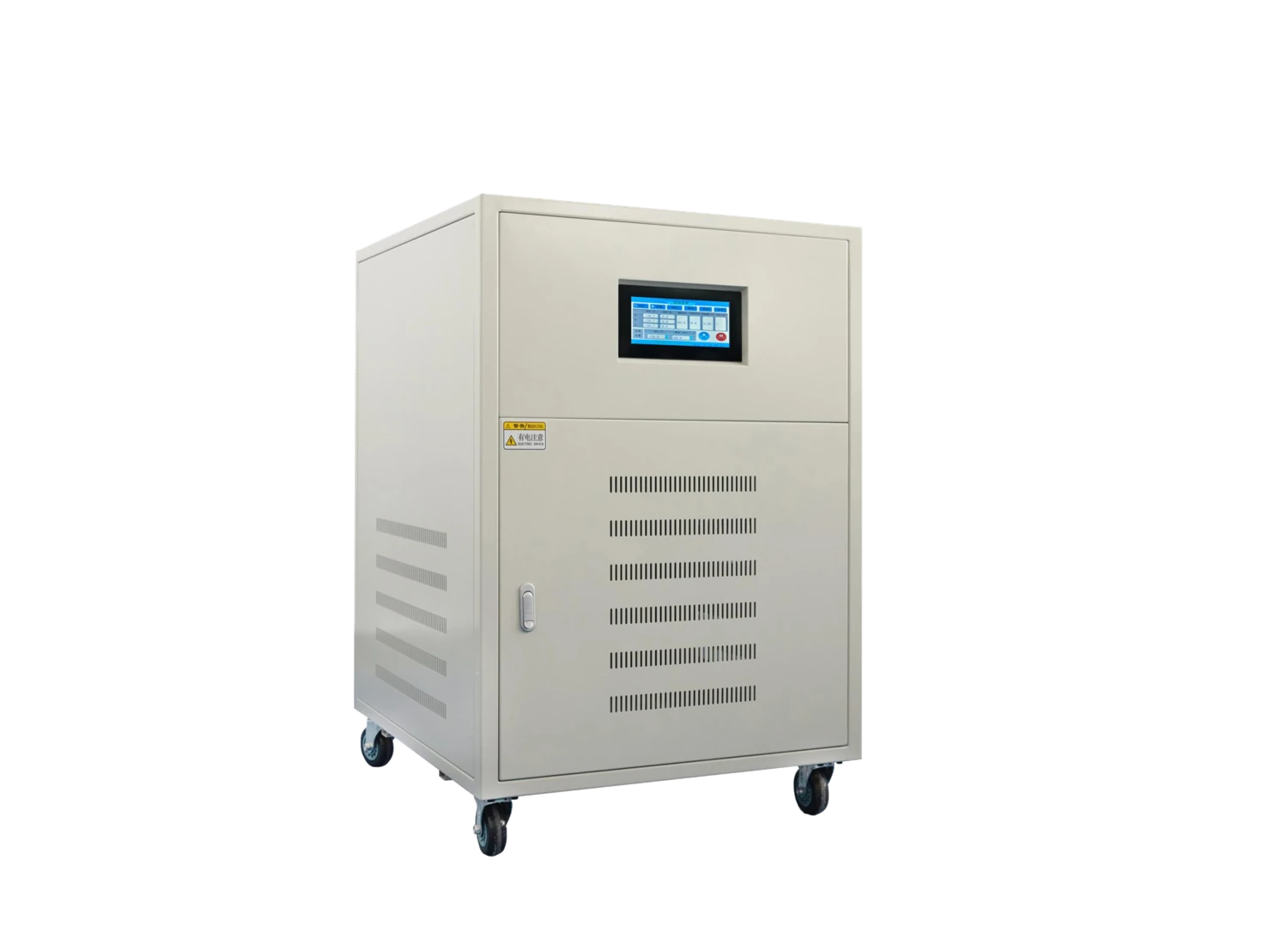
Create the AC supply the equipment requires
We separate the available input supply from the output the equipment needs. Where the frequency must change, power conversion provides a function that a passive transformer cannot. Voltage, frequency and the connected load then become coordinated requirements for the AC source.
The AC–DC–AC conversion principle
Our AC power-supply family uses the AC–DC–AC principle: rectification creates a DC stage, and an inverter produces the AC output. This functional path explains how input and output frequency can differ. The selected configuration defines the detailed conversion arrangement, filtering and any isolation requirement for the project.
Match the source to the complete equipment load
An AC power source supplies equipment according to its input requirements, including waveform, voltage, phase arrangement and startup demand. A motor variable-frequency drive is configured around a motor and its control duty. The two functions need different selection discussions even when both involve changing frequency.
For a machine containing electronics, heaters, controls and motors, we consider the complete input load and operating sequence. For speed control of an individual motor, the motor-control cabinet configuration is the relevant starting point. This distinction helps connect the power equipment to what the application actually needs to operate.
Coordinate input and output phase arrangements
We organize the source voltage, frequency, phase count and available neutral separately from the output requirements. The load's line-to-line and line-to-neutral references determine how its supply is described, while the site's feeder conditions shape the incoming interface.
Our family-level configuration discussion covers single-phase and three-phase input/output arrangements, with the combination aligned to the selected model and application. Terminal information, cable approach and the project one-line then describe the same power path. This is particularly useful for equipment moving between facilities, where the new site supply may differ from the machine's original installation.
Define the output points used in production or testing
| Input to the discussion | Configuration focus |
|---|---|
| Output voltage, frequency and phase | The required continuous operating points |
| Current, kVA and kW | Usable output at each point |
| Starting and transition sequence | Short-duration demand and output behavior |
| Waveform and load type | Measurement conditions and performance needs |
| Dwell time and repetition | Operating cycle and thermal duty |
For a production test, a sequence of required points is more useful than a broad range alone. We discuss the starting condition, transitions and time spent at each point so the configuration reflects the actual test cycle.
Consider current, real power and peak demand separately
Continuous output capability
Apparent power in kVA, real power in kW and output current describe different constraints. Power factor links apparent and real power, but both requirements belong in the selection. At a lower output voltage, maintaining the same kVA would require more current, so the current capability at that point matters.
Starting and nonlinear loads
Motor starting and electronic input circuits can create short peaks or a nonsinusoidal current waveform. We discuss RMS current, peak demand, duration and repetition together. Crest factor describes the relationship between peak and RMS current; it helps distinguish two loads with similar continuous demand but different waveform requirements.
Explore our ZFDP and ZFSP series
| Series | AC power-supply family | Capacity span | Model entries |
|---|---|---|---|
| ZFDP | Single-phase | 500 VA–45 kVA | 11 |
| ZFSP | Three-phase | 3–150 kVA | 11 |
The series pages present individual capacities and dimensions. We use the relevant entry as a starting point, then coordinate the input arrangement, required voltage/frequency points and load behavior. This connects the model comparison to the equipment's continuous and transient demand while also helping the layout team assess available space.
Bring control and protection interfaces into the configuration
We discuss local operation, external enable, status signals and any remote-control or sequence requirements alongside the electrical output. Where a project needs communication, the intended command authority and behavior after communication loss help define the interface. Isolation and output-neutral requirements also belong in the selected power arrangement.
A load capable of returning energy needs a separate discussion of that energy path. We consider the requirement explicitly rather than treating it as ordinary consuming-load duty. Overload, overtemperature and fault-response requirements are likewise coordinated with the application, including the intended output state and restoration procedure.
Plan the thermal path and application interfaces
Power electronics and magnetic components produce heat that must reach the cooling air or other designed cooling path. Airflow routes, enclosure layout and neighboring heat sources therefore affect installation. We discuss material and finish, cable entries, terminal access and replacement space with the equipment arrangement.
Shore-power requirements
For a shore-power application, the discussion also includes ship and shore voltages, frequency, grounding interface, protection and environmental conditions. The project's marine specialists coordinate the applicable system and approval requirements. We align the proposed AC-source interface with that project definition so its electrical and physical requirements enter the configuration together.
Our operating-point review and project documents
We work through the required output points with the load and measurement conditions that matter to the project. Where waveform performance is important, the load condition and measurement basis make that requirement meaningful. Agreed checks can then relate directly to the operating sequence.
Our technical equipment includes AC test supplies, a high-current load platform and temperature monitoring, supporting our power-equipment work. Project documents bring together nameplate, connection information, outline and agreed inspection records. We also discuss packing, handling, cooling access and operating information so the receiving and integration teams have a consistent equipment reference.
Discuss your AC power requirement
Start with the supply available at your site and the voltage and frequency your equipment needs. A load description or machine nameplate is enough to begin organizing the requirement. We can then work through continuous demand, startup behavior and any testing sequence.
Add phase and neutral requirements, installation conditions and available space as the project develops. Mention any isolation, remote-control or returning-energy requirement early. We use these inputs to discuss an AC-source configuration and the electrical, mechanical and documentation interfaces needed for integration.