
Busway and Tap-Off Units
We connect busway project discussions with the transformers, connection boxes and distribution cabinets at each end of the route. Source connections, branch loads and available space work together to shape a coordinated power-distribution arrangement.
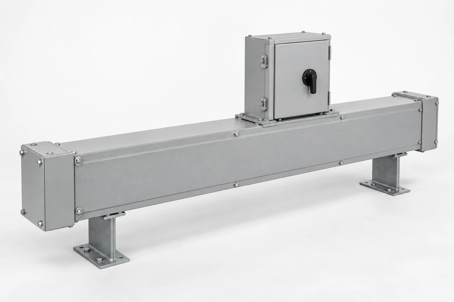
We coordinate the equipment interfaces around the selected busway system. System selection, supplied components and installation responsibilities are defined in the project arrangement, including any connection to an existing route.
Connect the source to the places power is needed
Busway, also called busbar trunking, carries power through enclosed conductors along a planned route. It can connect a source to a large load, distribute power through a production area or serve successive levels of a building. The application determines where power enters, where it branches and how the route fits the available space.
We start with the equipment interfaces: a transformer or incoming cabinet, the selected busway connection and the downstream loads. A busbar connection box may concentrate connections at a local boundary, while the busway carries them along the route. This distinction keeps the project layout and supply scope clear.
Coordinate the parts from feed unit to branch circuit
A complete route combines feed units, conductor sections, direction changes, joints, supports and end closures. Tap-off units connect branch loads at designated positions. We use that sequence to organize the equipment and cable interfaces around the selected system.
| Part | Function | Project interface |
|---|---|---|
| Feed unit | Brings power into the route | Source terminals and entry geometry |
| Sections and fittings | Carry power around the building | Lengths, bends and orientation |
| Joints | Connect designated sections | System-specific mating parts |
| Tap-off units | Supply branch circuits | Load, protection and outgoing cable |
| Supports and closures | Position and complete the route | Structure, access and environment |
Relate the load positions to electrical duty
Loads distributed along a route affect the current carried by each section. Their locations influence voltage drop and thermal duty as well as the total demand at the source. We connect those load positions with voltage, frequency, pole arrangement, neutral requirements and the upstream protective equipment.
Allow for changes in production
Moving a machine farther from the feed point changes its position in the electrical system even when its nameplate demand stays the same. New branches and simultaneous starts also change the duty. A reserved tap opening gives a connection location; available capacity depends on the complete source, route and load arrangement.
Our route coordination starts with the site layout
We discuss the route using segment references that can follow through into drawings, labels and packing information. Horizontal runs, vertical risers, offsets and cabinet entry positions each create different space requirements.
| Route feature | Load connection | Space consideration |
|---|---|---|
| Start, end and segment length | Source or receiving equipment | Connection and installation access |
| Horizontal or vertical section | Tap position and branch demand | Supports and service clearance |
| Bend, offset or penetration | Connection orientation | Structure and neighboring services |
| Future extension area | Expected additional load | Reserved route and access |
Final site dimensions and equipment locations are reconciled before the corresponding connection arrangement is released.
Compare conductors, insulation and housing as a system
Copper and aluminum conductors
Copper's conductivity can support a compact section, while aluminum's lower mass can influence handling and support loads. The required section, joint construction and thermal arrangement must be considered together. We relate material choices to the selected system and its equipment connections rather than comparing metal names alone.
Housing, insulation and joints
The enclosure protects and positions the conductor assembly, while insulation and supports maintain its designed separation. Dust, moisture, corrosion and ambient heat affect the construction discussion. Joint packs, covers and seals have specific mating relationships, so a material or component change can also affect connection dimensions and service access.
Match tap-off interfaces and future extensions
For an existing installation, the exact system series, revision, pole arrangement and connection geometry provide the starting point. We use those identifiers to discuss the interface between a tap-off, its outgoing circuit and the receiving cabinet.
Compatibility follows the selected system
Matching appearance, current rating or enclosure size does not establish that two tap-off or joint assemblies are interchangeable. Contact positions, mechanical engagement, interlocks and protective connections can differ. Keeping the correct part references with the route drawing helps later additions remain coordinated with the original system, instead of relying on a visual match.
Bring protection, metering and downstream cabinets together
Branch power
A feeder tap-off needs a defined load, protective function and outgoing connection. We connect those details with cable routing and the available fault-duty information so the branch interface can be coordinated with the upstream system.
Metering and local distribution
Where branch measurements are part of the project, the required values, display and communication signals belong in the configuration discussion. A connection to our distribution cabinets also needs matching terminal positions, cable space and circuit identification. Metering equipment, protective devices and the enclosure layout are distinct choices within that branch arrangement.
Coordinate supports, movement and building openings
Supports carry the route in its intended orientation and transfer its loads to the building. Long runs, vertical sections and building movement joints also affect where movement provisions belong. We bring these constraints into the equipment-interface discussion so connection locations are consistent with the physical route.
Work with the building layout
The responsible building professionals coordinate structure, fixings, penetrations, fire-stopping and weather details with the selected system. Access around joints and tap points must remain usable after other services are installed. Resolving these relationships on the layout helps avoid a connection that fits electrically but is obstructed in the building.
Keep delivery information tied to the route
Section numbers, package references and connection labels give the installation team a common way to identify the delivered arrangement. We coordinate the agreed interface drawings and document scope with the project so source and load connections remain traceable through delivery.
Installation and operating records
Handling and storage follow the selected equipment instructions, with joints and connection surfaces protected from damage. Qualified personnel assemble and commission the system using its specified procedures. The term plug-in does not mean a tap-off can be inserted or removed while energized. Joint checks, configuration changes and commissioning results remain linked to the route drawing for ongoing operation.
Plan the next connection with us
Start the discussion with a route sketch, the source equipment and the loads to be supplied. For an extension, include the existing system identity and the points where new equipment will connect. We can then focus the configuration conversation on terminals, cable space, branch functions and the installation environment.
Drawings and relevant photographs can be exchanged as the project develops. Keeping the final route, part references and load schedule together also supports future maintenance and expansion decisions. Any addition can then be considered against both the connection interface and the electrical duty of the existing route.