
Transformers for Solar and Energy Storage Interfaces
We work with photovoltaic and energy storage project teams to configure the transformer interface between converters and the AC system. Inverter or PCS requirements, power-flow patterns and site conditions guide our discussion of windings, capacity, thermal duty and installation.
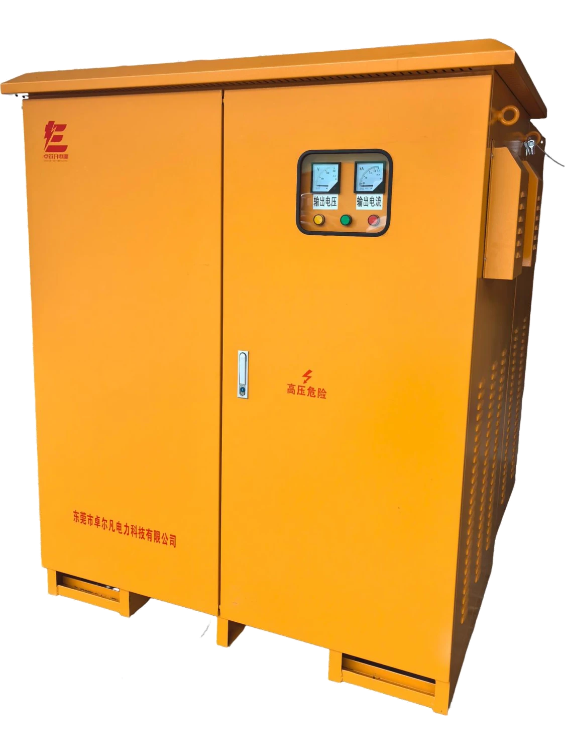
Place the transformer within the power path
Photovoltaic generation
In a PV arrangement requiring an external transformer, power flows from the inverter through the transformer toward the AC distribution and connection point. We develop the transformer configuration around the inverter's AC terminals and the receiving system.
Energy storage
A storage arrangement can transfer power in both directions between the PCS and AC system during charging and discharging. The selected architecture determines whether a transformer is needed and how it connects. Our work focuses on the transformer and agreed cabinet interfaces, with the converter, batteries and plant functions coordinated by the wider project team.
Match the design discussion to the operating profile
| Design input | Photovoltaic project | Storage project |
|---|---|---|
| Power cycle | Generation, curtailment and energized idle periods | Charge, discharge, transitions and standby |
| Converter interface | Inverter AC requirements | PCS requirements in each operating direction |
| Current demand | Active and reactive operating envelope | Operating envelope across charge/discharge states |
| Thermal focus | Daily generation cycle and site conditions | Duration and repetition of demanding states |
We use the expected schedule to connect the application's operating pattern to winding duty and cooling. Peak power and hours spent at each load level answer different design questions.
Develop the configuration with the converter team
The inverter or PCS model and its transformer-interface requirements establish the starting point. We discuss the required voltage, winding arrangement, impedance and any restrictions associated with its AC interface. Where several converters share equipment, their combined operating arrangement also enters the discussion.
This collaboration connects transformer design decisions to the actual converter rather than the application name alone. A change in converter model or firmware-related operating requirements may require another interface review. Keeping the equipment references and project one-line aligned gives our transformer work a clear electrical context throughout configuration and integration.
Turn interface requirements into design decisions
| Interface | Project input | Design effect |
|---|---|---|
| Voltage and frequency | Converter and AC-system values and ranges | Winding ratio and magnetic duty |
| Connections and neutral | Converter restrictions and system arrangement | Windings, terminals and grounding interface |
| Impedance | Converter and protection-design requirements | Electrical interaction and voltage behavior |
| Current waveform and direction | Operating envelope and load profile | Winding duty and thermal assessment |
| Installation | Environment, cable routes and access | Enclosure, cooling and physical layout |
The schedule keeps electrical and mechanical decisions connected to the same project configuration.
Address waveform and directional loading
Current waveform and heating
Converter current can differ from a simple sinusoidal load. Waveform information across the intended operating range helps us discuss additional winding and thermal demands. The relevant information includes current magnitude, harmonic content, imbalance and the duration of each operating condition.
Charging and discharging states
For storage, we consider both power directions and the transitions between them. Active-power values alone do not describe the full current demand when reactive operation is also required. We develop the transformer requirement around the specified converter conditions; the isolation transformer family explains the underlying separate-winding principle.
Connect losses and cooling to the daily cycle
No-load losses matter while a transformer remains energized, including idle periods. Load-related losses vary with operating demand. A daily profile therefore helps explain energy use over time, while the most demanding sustained condition helps frame the thermal discussion. We consider both when developing the project requirement.
Ambient temperature, altitude, enclosure exposure and available cooling affect the installation. Sound requirements also need a defined operating and measurement context. We discuss the required loss, temperature and sound information with the project team so the selected configuration addresses the actual environment and duty, with any agreed values tied to those conditions.
Bring winding construction and enclosure layout together
The core provides the magnetic path; conductor dimensions and resistance affect winding losses and heating. Copper and aluminum involve different cross-sections and terminal arrangements. Insulation construction and cooling then work together to manage the electrical and thermal stresses of the selected duty.
We coordinate the physical arrangement around cable approach, terminal access, ventilation and replacement routes. If the transformer shares a package with other equipment, its heat contribution belongs in the combined thermal assessment. Adjacent battery-cabinet requirements have their own battery and environmental interfaces, which the project layout needs to accommodate alongside the transformer.
Coordinate the transformer with the AC system
We align the transformer connections and equipment information with the project's one-line and AC distribution arrangement. Source characteristics, transformer impedance and the converter's operating modes inform the project specialists' protection and grounding work.
The same interface references help coordinate cables, switching equipment and control information across the package. System-level grid connection, storage safety and authority requirements remain with the responsible project specialists. Keeping our transformer interfaces clear supports that work while giving the cabinet and installation teams a consistent basis for their part of the project.
Our manufacturing and project documents
Our transformer manufacturing capabilities include wire and foil winding, vacuum pressure impregnation and high-temperature ovens. Core-loss and interturn testing, a high-current load platform, AC supplies and temperature monitoring support our production and technical work. We connect these capabilities to the selected winding, insulation and operating requirements.
Project documents bring together connection and terminal drawings, outline, nameplate and agreed inspection records. We also discuss packing, handling and receiving information for the installation team. These documents keep equipment identification and interface revisions aligned through delivery and integration, including any agreed project-specific checks.
Discuss your PV or storage transformer
Start with the inverter or PCS model, the AC-system voltage and the application. A one-line diagram and an outline of the generation or charge/discharge cycle help us understand the power path and develop the next configuration questions.
Add the required capacity, frequency, site environment and installation space as they become available. We work through winding connections, converter requirements, thermal conditions and physical interfaces with your team. For projects with defined loss, temperature or sound requirements, include those targets in the initial discussion so they enter the configuration from the outset.