
ZFSP Three-Phase Variable-Frequency AC Sources
Our ZFSP three-phase AC power sources cover 11 models from 3 to 150 kVA. We connect model selection to your output voltage and frequency points, per-phase loads and the operating process of the equipment being supplied.
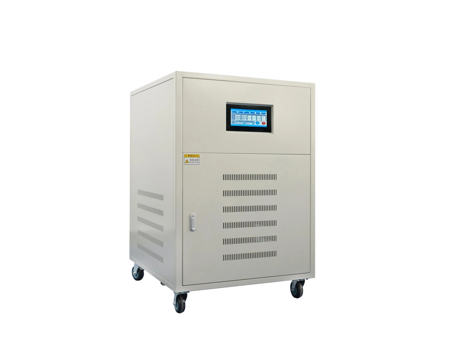
We develop the selected ZFSP configuration around the available input supply and the required three-phase output. The load schedule, connection arrangement and test conditions define the project discussion.
Explore our 3–150 kVA ZFSP model range
Our 11 ZFSP models give you a range of capacities for three-phase equipment supply and testing. Compare the model, capacity and dimensions together to begin planning the electrical duty and installation space.
Bring the selected model into the discussion
A model inquiry carries the model identifier and capacity into your request. Add the equipment you intend to supply and the output conditions it needs. For an existing test station, the current load schedule and installation layout are useful starting points. We can then discuss the selected size alongside input supply, per-phase current and the practical connection arrangement.
| Model | Capacity | Dimensions (mm) | Inquiry |
|---|---|---|---|
| ZFSP-3303 | 3 kVA | 620 × 400 × 920 | |
| ZFSP-3310 | 10 kVA | 620 × 400 × 920 | |
| ZFSP-3315 | 15 kVA | 620 × 400 × 920 | |
| ZFSP-3320 | 20 kVA | 620 × 400 × 920 | |
| ZFSP-3330 | 30 kVA | 770 × 500 × 1100 | |
| ZFSP-3345 | 45 kVA | 770 × 500 × 1100 | |
| ZFSP-3360 | 60 kVA | 850 × 660 × 1180 | |
| ZFSP-3375 | 75 kVA | 850 × 660 × 1180 | |
| ZFSP-33100 | 100 kVA | 850 × 660 × 1180 | |
| ZFSP-33120 | 120 kVA | 1200 × 800 × 1950 | |
| ZFSP-33150 | 150 kVA | 1200 × 800 × 1950 |
No matching model. Clear the search or describe your required capacity in an inquiry.
Coordinate the input with the available site supply
We define the input connection separately from the three-phase output requirement. Available voltage, phase and wire arrangement, frequency and supply variation describe the source-side conditions for the selected configuration.
Connect the feeder to the equipment layout
The source transformer or feeder capacity, upstream protection and earthing arrangement influence the installation. Cable approach and connection access also need to work with the unit's physical position.
The agreed connection drawing links these inputs to the AC source and its load. Qualified personnel use that arrangement to design and install the electrical connections.
Define line voltage, phase voltage and neutral use
We distinguish voltage between phase conductors from voltage between a phase and neutral. These values describe different connections, so the equipment requirement needs a clear measurement basis.
The output arrangement also depends on whether the load uses a neutral and what current that conductor must carry. Single-phase branches within a three-phase installation make this part of the configuration especially relevant.
Phase relationships
Phase sequence and any particular phase-angle requirement belong with the output schedule. If a test needs separate adjustment of individual phases, we discuss that as a specific control requirement alongside the selected model and operating points.
Review each phase alongside the total capacity
We use per-phase information to understand how the total demand is distributed. A three-phase kVA rating does not make the entire capacity available on one phase; unequal loads and neutral current need their own consideration.
| Load detail | Information to discuss | Configuration focus |
|---|---|---|
| Each phase | Voltage basis, RMS current, kW and duty | Per-phase operating requirement |
| Total demand | Simultaneous loads and power factor | Total apparent and real power |
| Unequal loading | Single-phase branches and duration | Imbalance and neutral current |
| Starting events | Peak demand and simultaneous starts | Transient duty and recovery |
Map voltage and frequency to the operating duty
We discuss the minimum, nominal and maximum output points your equipment needs, with current and duration at each point. This connects the selected capacity to the required operating envelope.
Continuous operation and changing conditions
An extended supply duty differs from a short test or repeated transition. Steps, ramps and brief peaks are therefore described separately when the process requires them.
Nonlinear loads can add repetitive peak-current demand to the RMS current requirement. Including that behavior in the load schedule helps us discuss the electrical and thermal conditions together, with any expansion requirement kept distinct from the current process.
Define three-phase output quality at the load
Voltage and frequency tolerances, waveform requirements and phase relationships are discussed at the operating points relevant to your equipment. We identify whether the required results apply to each phase separately and how the load will be connected during the check.
Balanced and unbalanced conditions
A balanced-load result describes a different operating condition from a test with unequal phase currents. Where both matter, the project schedule should define both arrangements.
Measurement location, connection leads, ambient conditions and timing after a load change also affect comparison. We align these details with the required records so results refer to a clearly described setup.
Discuss reverse energy and process control needs
Some motors, converters or test arrangements can return energy toward the supply. We include that behavior in the application discussion because it affects the suitable source arrangement and the required protective interfaces.
Operating and fault states
The process should define the required output state after overload, an interrupted input or another protective event. A restart may need an operator action or a coordinated response from the wider test system.
Remote commands, interlocks, status feedback and any automatic sequence are also project requirements to discuss. Their function and stop behavior need to align with the equipment being supplied and the selected configuration.
Arrange terminals, cooling and maintenance space
We coordinate the model's external arrangement with cable entry, terminals, mounting and access. Labeled dimension directions and a defined connection layout help translate the model dimensions into a workable installation.
Power-conversion losses create heat inside the unit. Output kVA is not the heat released into the room, so the ventilation discussion uses operating losses and the intended duty. Air paths need clearance from cables, walls and neighboring equipment.
Enclosure finish, insulation and conductor interfaces are considered with temperature, contamination and the installation environment. Equipment mass, packed mass and shipping dimensions then support handling and delivery planning for the selected arrangement.
Develop ZFSP project documents and delivery details
We connect the agreed output points and per-phase load schedule to the connection drawing, mechanical layout and equipment identification. Required checks and records refer to those same conditions.
Project-specific measurement, calibration or destination documentation can be defined with the order scope. The supplied accessories, operating information and packing arrangement are identified alongside the selected model.
Carry the configuration into operation
Receiving checks match the equipment and parts to the order. Qualified installation and commissioning follow the agreed instructions, while retained drawings and model identification support later configuration discussions. Accessible cooling paths and service areas also make routine inspection and cleaning more practical.
Discuss your ZFSP model and phase loads
Start with the model or required capacity, input supply and output voltage and frequency points. A summary of each phase's load, any single-phase branches and startup demand helps us focus the next discussion.
Add quantity, destination and space constraints. Detailed test schedules can follow as the configuration develops. For single-phase output, explore our ZFDP models; our AC frequency converter range covers the wider application choices.