
Battery Module Cabinets
We develop cabinet and rack arrangements around your specified battery modules. Module supports, cable routes, cooling interfaces and service space come together in a layout that fits the equipment and installation.
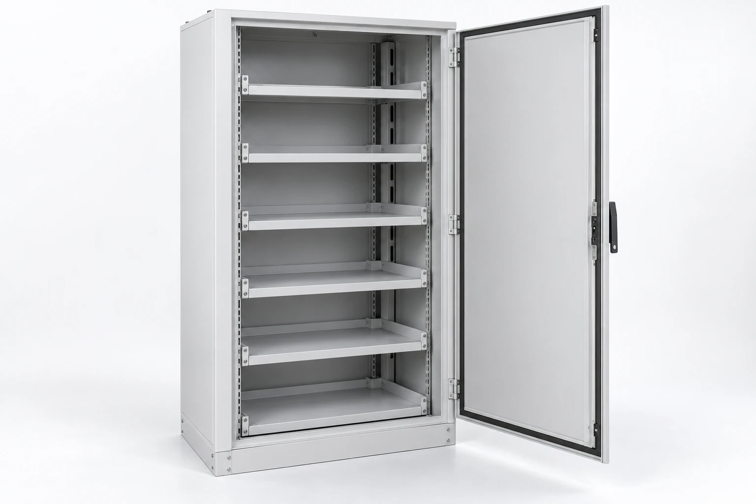
Our cabinet configuration starts with the selected modules and the system design. We coordinate the mechanical arrangement and agreed interfaces with the battery, conversion and integration teams.
Define the cabinet within the system
A battery storage cabinet provides the structure around a specified module arrangement. We use a clear scope description so the mechanical work connects correctly to the equipment and electrical functions in the project.
| Level | Main function | Configuration focus |
|---|---|---|
| Cabinet or rack | Housing and module support | Loads, layout and access |
| Battery subsystem | Specified modules and associated connections | Operating limits and DC interfaces |
| Complete energy storage system | Coordinated storage, conversion and control | System performance, protection and installation |
The functional path runs from battery modules through the DC connection and protection arrangement to the power conversion system, then to the project AC interface. BMS and system controls provide the associated monitoring and control connections.
We distinguish the battery cabinet around the DC modules from a transformer at an applicable AC interface. Where the selected converter architecture calls for AC voltage matching or electrical separation, our solar and energy storage transformer interfaces connect that requirement to the AC side of the project.
Use the module specification to shape the cabinet
Dimensions and support details
We use the module model, revision, dimensions and mass to establish the cabinet layout. Specified mounting orientation, support points and handling clearances help determine rack spacing and the access route.
Power, energy and operating duty
Power in kW describes a rate of energy transfer; energy in kWh relates to the operating requirement over time. Capacity in Ah needs its associated voltage and rating basis. These quantities guide the system discussion but do not define the cabinet's mechanical capacity.
Charge and discharge duty, backup objectives and module operating limits connect the system requirement to the layout we develop.
Coordinate mechanical, conversion and control interfaces
We connect the enclosure arrangement to the battery and conversion equipment rather than treating each as an isolated item. The battery team provides module limits and mounting requirements; the conversion team defines the relevant DC operating range and connection arrangement.
BMS signals, communication requirements and control responses need coordination with the system integrator. Cabinet drawings then locate the equipment, access points and routes needed by that agreed architecture.
For an inverter battery cabinet project, identifying whether the inverter shares the enclosure or connects externally helps establish heat sources, cable paths and the working space around each device.
Plan space around DC connections and BMS links
The electrical design uses minimum and maximum DC voltage, continuous current, peak current and its duration. Power-flow direction and the connection limits of the conversion equipment also affect the arrangement.
We coordinate physical space for the agreed terminals, cable or bus routes and protective components. Disconnects, contactors and any precharge function belong to the specified system circuit, with their locations and access requirements carried into the layout.
BMS communication needs its defined protocol, version and signal list. The system team determines responses to communication loss and abnormal conditions; our interface discussion identifies the associated wiring routes and cabinet provisions.
Support modules and preserve their removal path
We review the module load at its actual support points. Shelf span, rack fixing and base support need to reflect the distribution of weight, while the installation team coordinates the floor or supporting structure.
Structure and materials
Frame rigidity, surface protection and insulating supports serve different purposes. The chosen arrangement also needs room for cables or bus connections without compromising required electrical clearances.
Module access
The door opening and clear space in front of the rack influence module removal. Handles, cables and nearby equipment can obstruct that path. We consider these details with the specified handling method before the cabinet layout is settled.
Bring thermal and protective provisions into the layout
We use the selected battery and conversion equipment's heat-loss and temperature data to coordinate thermal interfaces. Heat generation changes with duty, so the module arrangement, airflow channels and temperature-sensor positions need to reflect the intended operation.
Our cabinet cooling configuration connects these inputs to the cooling method, auxiliary supply and maintenance space. Where cooling services or sensors cross the cabinet boundary, their connections belong on the interface schedule.
Protective measures depend on the battery chemistry, system arrangement and installation. The integrated design determines the required provisions within the cabinet and at the site; a metal enclosure alone does not establish fire performance.
Connect cabinet details to the complete system requirements
We coordinate enclosure details with the selected battery, BMS and conversion equipment as one defined arrangement. A component change then has a clear route back into the cabinet drawings and interface schedule.
Module and conversion changes
A replacement module can change mass, support-point locations, terminal projection and the space needed for removal even when its energy rating is similar. We revisit shelves, fasteners and cable access around that actual geometry. A changed power conversion system can alter the DC operating window, current requirements and heat sources; the system team confirms the electrical limits while we coordinate the resulting connection space and thermal interfaces.
Communication and service changes
A different BMS protocol, connector or signal assignment affects the communication interface and its cable route. We keep connector access, cable separation and equipment identification aligned with the revised signal schedule. Recording these effects together helps the integrator preserve service access while resolving compatibility in the system design.
Develop useful cabinet drawings and delivery records
Our cabinet documents identify the agreed arrangement, dimensions, module supports, openings and selected mechanical accessories. Drawing revisions connect those details to the equipment configuration being integrated.
Mechanical acceptance can focus on dimensions, supplied parts, access and the agreed load arrangement. Electrical, control and performance checks for a fitted system follow the integrator's defined procedure and project scope.
Keeping the cabinet drawing, component references and resolved changes together gives the installation team a practical record. It also helps distinguish a mechanical change from a change that needs wider electrical or system review.
Plan packing around the actual shipment contents
We discuss shipping dimensions, package arrangement, support points and separately packed parts with the cabinet configuration. An empty enclosure and a shipment containing battery modules need different logistics planning.
Where batteries are included in the project shipment, the designated logistics parties handle the applicable packing, transport and storage requirements for the actual contents and route. Package identification helps connect receiving checks to the correct equipment.
The operating system's instructions and site plan define abnormal-condition reporting and emergency response. Those provisions remain connected to the specified battery system and its qualified operating team.
Discuss your module and installation layout
Start with the module specification, quantity and available installation space. We can then discuss the cabinet structure, access route, DC connection zones and cooling interfaces around those inputs.
For an existing installation, include the fitted module and cabinet references. Future module changes need a review of mechanical fit, connections and system compatibility, even when the proposed module has a similar size or capacity. This information helps us focus the cabinet discussion on the configuration you intend to use.