We explain the engineering choices behind industrial power equipment, electrical cabinets and meter boxes. Explore six articles with practical comparisons and clearly stated examples, then connect the ideas to your equipment and installation.
Search the six engineering articles below by topic. Product model tables and project documents are organized in our technical resources.
No matching topic. Try a broader term or
Start with the decision your project needs
We organize these articles around questions that change an equipment configuration. Does a machine need electrical separation or only a different voltage? Does a cabinet need more airflow or a different cooling method? Does a meter carry service current directly or receive a CT signal? Answering the function first makes the later capacity and layout discussion more useful.
Compare, calculate, then configure
Our worked examples state their assumed voltages, currents and operating conditions. We use them to explain a method, while the selected equipment follows your actual load and site requirements. For capacities and dimensions, visit our technical resources and model tables; for the equipment families themselves, browse our products.
Choose separate or shared transformer windings
We begin transformer selection with the required relationship between the supply and load circuits. Separate windings provide galvanic isolation. An autotransformer shares a winding portion, so its source and load remain electrically connected. The choice affects grounding, neutral interfaces and the way the transformer fits into a machine power system.
Our comparison explains those differences alongside voltage ratio, material use and starting behavior. We also show why neither winding arrangement changes frequency, so a voltage mismatch and a frequency mismatch need separate attention.
We choose between an isolation transformer and an autotransformer by the circuit relationship the equipment needs. An isolation transformer has electrically separate windings; an autotransformer shares a winding section between source and load. We use that difference first, then compare voltage, current, space and operating duty.
Calculate load kVA and identify the demanding operating state
We turn voltage and current data into an initial apparent-power requirement, then examine what the simple total leaves out. Single-phase and balanced three-phase calculations use different voltage references. Power factor connects electrical kW to kVA, while motor efficiency connects shaft output to electrical input.
Our sizing article includes arithmetic you can reproduce and explains how simultaneous starts, uneven phase loading and nonlinear current change the selection discussion. The result is a useful load brief for a transformer inquiry, with expansion identified separately from today's demand.
We calculate an initial transformer load from voltage and current, then check the operating conditions behind that number. For a single-phase load, kVA = RMS volts × RMS amps ÷ 1,000. For a balanced three-phase load, kVA = √3 × RMS line-to-line volts × RMS line amps ÷ 1,000. Starting events, phase imbalance and the installation still shape the final configuration.
We separate fixed voltage conversion, automatic voltage regulation, AC frequency conversion and motor speed control. Each addresses a different operating need. A stabilizer can address a changing voltage within its configured range; a transformer retains the source frequency; an AC source is specified around the output required by the complete load.
Our comparison helps connect an imported machine or test station to the right discussion. We include starting loads, bypass behavior and the difference between supplying mixed equipment and controlling an individual motor.
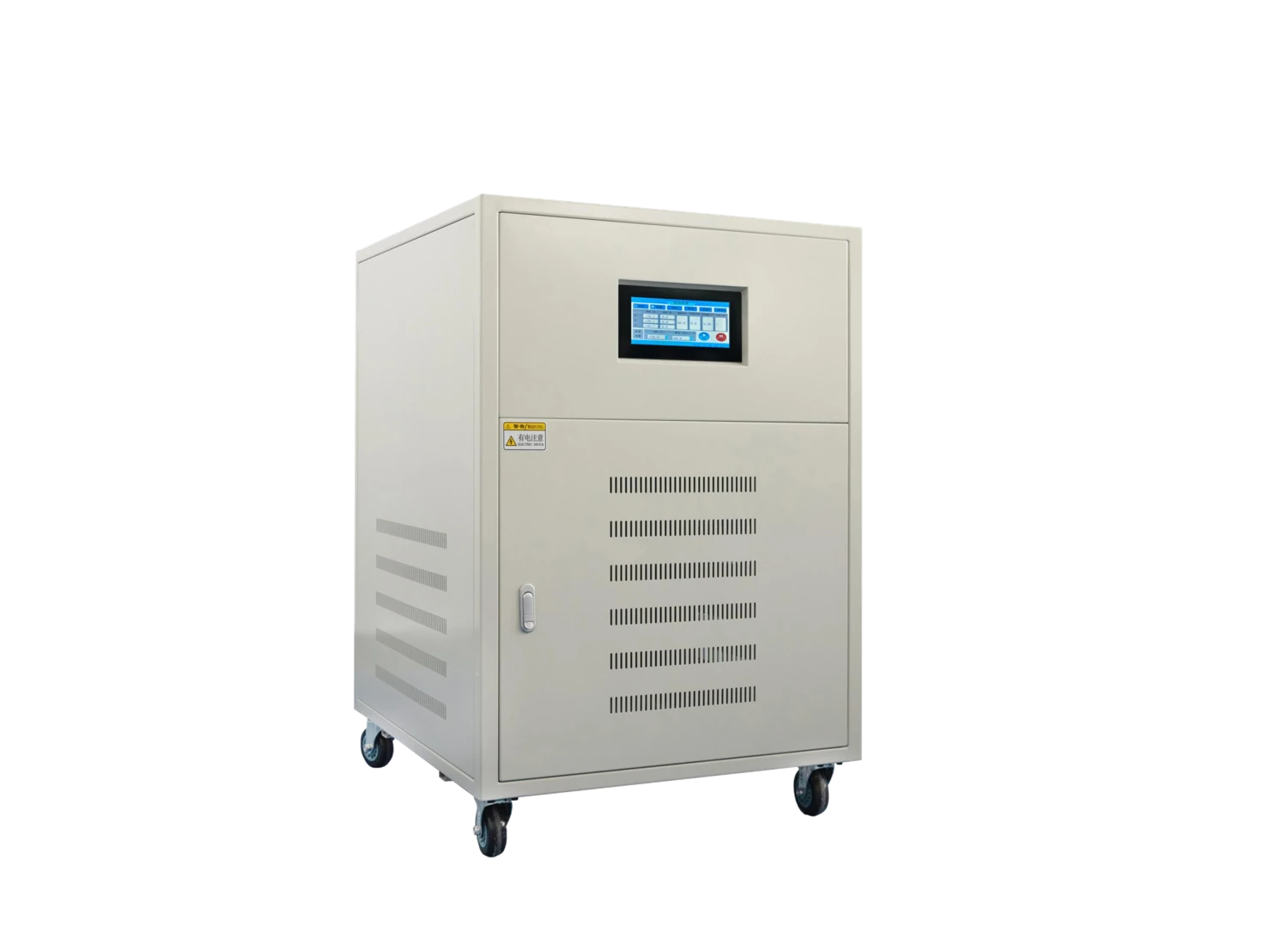
Our three-phase AC power supply; the required output and load conditions guide configuration.
We compare four power functions through two practical examples: an imported machine with a supply mismatch and a test station that needs different AC operating points.
Relate cabinet materials to the installation environment
We consider a cabinet's material together with its finish, openings, seals and hardware. Coated steel, stainless steel and nonmetallic construction respond differently to mechanical loads, cleaning, moisture and corrosion exposure. A material name alone does not describe the complete assembly.
Our materials and cooling article connects these choices to the devices inside the enclosure and the place it will operate. We explain why cable-entry details, mounting access and maintenance conditions belong in the same discussion as the sheet or molding material.
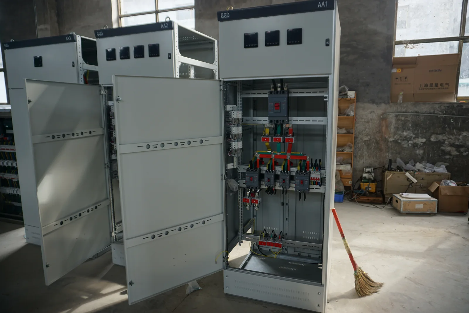
Cabinet structure, equipment space and access form part of the same layout discussion.
We hold the equipment and its assumed 140 W internal heat loss constant, then compare how dust, humidity and high ambient temperature change the enclosure decisions.
Separate equipment output from the heat inside the cabinet
We use component losses to describe a cabinet's heat load. A drive supplying a motor does not release the motor's whole output power into the enclosure. The internal losses, ambient conditions, available surfaces and airflow paths together define the thermal problem.
Keep sealing and service access in the thermal decision
Air exchange can remove heat when surrounding air is suitable and cooler than the permitted internal temperature. Contamination, high ambient temperature or a closed enclosure can lead to a different approach. We connect those conditions to cabinet cooling interfaces, filter or cooling-unit access and the maintenance space around the installation.
Understand direct and CT metering before sizing the box
We distinguish the meter's measurement function from the enclosure around it. A direct-connected meter carries the specified service current through its current path. A CT-operated arrangement presents the meter with a measurement signal, introducing ratio, burden, polarity and test-access questions.
Our metering article explains these relationships and how they shape compartment separation, cable space and utility interfaces. We keep local service requirements visible without assuming a universal current threshold or treating every meter socket as interchangeable.
We follow the load current and measurement signal separately, then use simple illustrative calculations to show why CT ratio, secondary wiring and cabinet layout belong in one project discussion.
Turn a process sequence into a control-cabinet layout
We start with what the process measures and how it should respond. Commands, permissives, feedback and recovery states identify the devices and signals that need space and connections inside a cabinet. An input/output count is useful, but the operating sequence explains when the connected loads act together.
Our control-cabinet planning article follows that process into control power, terminals, cable routes, heat and service access. It gives purchasing and engineering teams a common way to describe a machine panel while keeping the system's safety and programming requirements tied to the responsible project design.
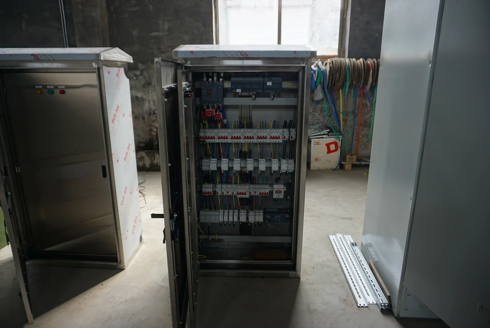
Control hardware, terminals and wiring form a coordinated cabinet layout. The article uses a separate hypothetical machine example.
We follow a hypothetical conveyor and packaging station from its operating sequence to signals, power, terminals and layout, then trace what changes when one sensor is added.
Tell us which equipment or operating problem led you to the article. A machine nameplate, supply description or simple layout can be enough to begin. We work through the source, load and installation details with you, then connect them to the transformer, stabilizer, AC source, cabinet or meter-box configuration.
Include the article topic, quantity, destination and project stage where known. Our application pages show how the equipment interfaces connect to the wider system, and our team can discuss the drawings or technical information needed for your next decision.