
ZFSG Three-Phase Isolation Transformers
Our ZFSG three-phase isolation transformers span 5–500 kVA across 21 models. Choose a capacity for your application, then work with us on the input and output configuration, load conditions and installation layout.
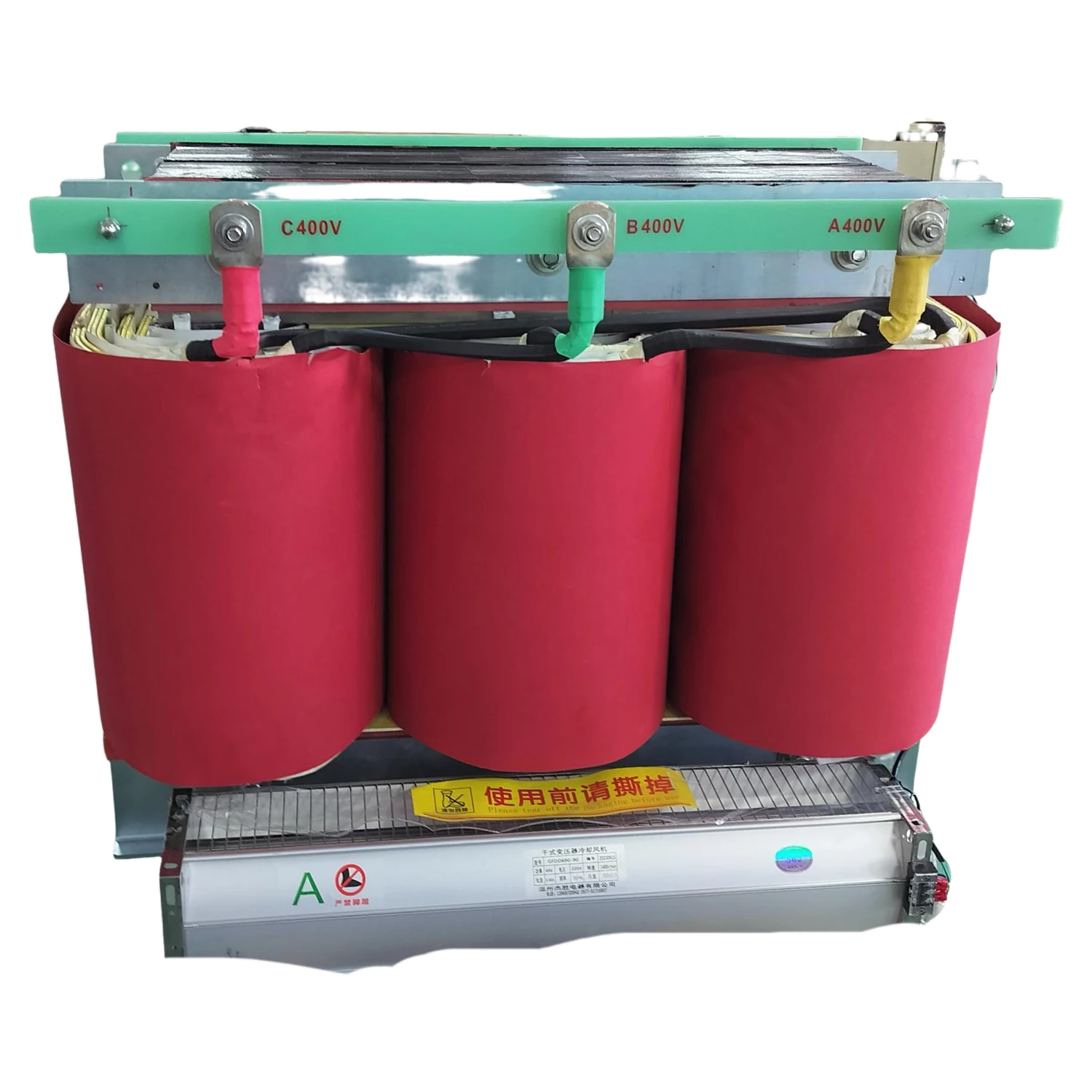
Our model range gives you a practical starting point for capacity and space planning. We develop the electrical connections, construction details and installation documents around the selected model and your application.
Explore our ZFSG model range
Our 21 ZFSG models cover capacities from 5 to 500 kVA. The table brings capacity, voltage notation, dimensions and weight together so you can compare models against the load and available installation space.
Start with the closest capacity
Select a model row to begin an inquiry with its model and capacity already identified. You can then describe the equipment it will feed and any particular voltage, connection or dimensional requirements. For a replacement project, the existing nameplate and installation drawing help us connect the selected model to the available supply and mounting arrangement.
| Model | Capacity (kVA) | Voltage | Enclosure dimensions (mm) | Weight (kg) | Inquiry |
|---|---|---|---|---|---|
| ZFSG-5 | 5 | 380V/220V | 270 × 410 × 370 | 20 | |
| ZFSG-8 | 8 | 380V/220V | 300 × 450 × 420 | 23 | |
| ZFSG-10 | 10 | 380V/220V | 300 × 450 × 420 | 30 | |
| ZFSG-12 | 12 | 380V/220V | 350 × 500 × 500 | 34 | |
| ZFSG-15 | 15 | 380V/220V | 350 × 500 × 500 | 37 | |
| ZFSG-20 | 20 | 380V/220V | 350 × 500 × 500 | 47 | |
| ZFSG-25 | 25 | 380V/220V | 420 × 600 × 580 | 52 | |
| ZFSG-30 | 30 | 380V/220V | 420 × 600 × 580 | 57 | |
| ZFSG-40 | 40 | 380V/220V | 420 × 600 × 580 | 77 | |
| ZFSG-50 | 50 | 380V/220V | 450 × 680 × 710 | 83 | |
| ZFSG-60 | 60 | 380V/220V | 450 × 680 × 710 | 93 | |
| ZFSG-80 | 80 | 380V/220V | 550 × 800 × 820 | 123 | |
| ZFSG-100 | 100 | 380V/220V | 550 × 800 × 820 | 135 | |
| ZFSG-120 | 120 | 380V/220V | 1050 × 750 × 1400 | 145 | |
| ZFSG-150 | 150 | 380V/220V | 1050 × 750 × 1400 | 198 | |
| ZFSG-200 | 200 | 380V/220V | 1050 × 750 × 1400 | 275 | |
| ZFSG-250 | 250 | 380V/220V | 1200 × 800 × 1500 | 296 | |
| ZFSG-300 | 300 | 380V/220V | 1200 × 800 × 1500 | 360 | |
| ZFSG-350 | 350 | 380V/220V | 1200 × 800 × 1500 | 420 | |
| ZFSG-400 | 400 | 380V/220V | 1350 × 850 × 1500 | 560 | |
| ZFSG-500 | 500 | 380V/220V | 1350 × 850 × 1500 | 610 |
No matching model. Clear the search or describe your required capacity in an inquiry.
Provide separate windings between supply and load
Our ZFSG series uses the isolation-transformer principle: energy passes through magnetic coupling between separate windings. This makes the transformer a defined interface between the incoming three-phase supply and the downstream equipment.
We discuss that interface in the context of the whole installation, including distribution, protection and the required earthing arrangement. Voltage matching and winding separation have different roles, and the transformer does not change supply frequency. When the load includes a distribution cabinet, its incoming connection and downstream circuits help define the required output arrangement.
Configure your input and output voltages
We use your site supply and equipment requirement to define primary and secondary voltages. The table's 380V/220V notation is retained as a model reference; the project electrical schedule specifies the role and measurement basis of each required voltage.
| Project input | What we coordinate |
|---|---|
| Incoming supply | Primary voltage, line or phase basis, frequency and variation |
| Equipment voltage | Secondary voltage, connection and neutral requirement |
| Three-phase system | Winding arrangement and phase relationship |
| Operating duty | Capacity and thermal conditions for the application |
Coordinate terminals with the site cables
The connection drawing links the winding arrangement to accessible terminals and their identification. We discuss cable material, conductor sizes, parallel runs and entry direction so the terminal space suits the intended connections.
Neutral and protective connections
Where the load needs a neutral, that requirement belongs in the electrical schedule from the start. Protective bonding and earthing are coordinated with the installation design.
Fault-level and protection studies may also need transformer impedance, energization behavior and other selected-unit data. We align the required information with the project documentation while qualified designers determine the protection arrangement.
Match the capacity to load behavior
A continuous load, a motor starting cycle and a rectifier load can place different demands on the same kVA size. We use the operating description to discuss simultaneous demand, short-duration events and the required duty.
Starting and nonlinear loads
Motors, drives and electronic equipment can introduce starting current or nonsinusoidal current. Their characteristics help define the configuration; adding equipment nameplate kW alone does not establish transformer kVA.
Ambient temperature, altitude, ventilation and future load changes also influence the selection. Separating the present duty from expansion requirements gives a clearer basis for choosing among the 21 models.
Balance magnetic, conductor and thermal requirements
Core design influences magnetic performance and no-load loss. Winding conductor dimensions and connections influence resistance, current handling and heat generation. The insulation system and cooling arrangement work with these choices to meet the intended duty.
We discuss specific conductor, insulation or finish requirements as part of the model configuration. Material selection also interacts with available space, terminal design and the operating environment.
Losses and temperature rise
Loss values describe energy dissipated; temperature rise describes the resulting thermal behavior under defined conditions. Keeping both in the project schedule helps coordinate ventilation and any operating-cost comparison.
Fit the transformer into the installation
Table dimensions and weight support an initial space and handling comparison. We then coordinate the general arrangement drawing with the actual installation, including the labeled dimension directions, mounting points, cable approach and access clearances.
The route to the final position matters as well as the space around the installed unit. Doorways, changes in direction and the supporting structure can affect the delivery arrangement.
Equipment weight and packed shipping weight have different uses. Packing dimensions, lifting provisions and any separately supplied items are discussed with the selected construction so transport planning follows the unit being delivered.
Connect ZFSG configuration to our manufacturing process
Our transformer manufacturing facilities include foil and wire winding equipment, vacuum-pressure impregnation equipment and drying ovens. These capabilities support the winding, insulation and drying processes used for the agreed transformer construction.
Core-loss and interturn testing equipment, load-test resources and temperature monitoring support our production and project verification work. We define the required checks and documentation with the selected model and application.
Destination standards and project-specific documents can be included in that discussion early. The resulting electrical schedule, drawing and nameplate details give production and the receiving team a common configuration reference.
Prepare delivery and installation information
We coordinate the agreed test records, connection drawing, nameplate information and packing details with the order. Any particular inspection points or witnessed checks are defined in the project scope before production.
Receiving and continued use
At delivery, model identification, accessories and visible condition can be checked against the order documents. Qualified personnel carry out installation and commissioning using the selected unit's instructions.
Access for inspection, cleaning and terminal maintenance should remain available after installation. Retaining the final drawing and equipment identification makes later configuration discussions more precise.
Discuss a ZFSG model with us
Select a model in the table or send your required capacity and application. Input and output voltages, frequency and a short load description are useful starting points; we can then work through connections, environment and installation space.
Include quantity, destination and any existing drawing or project specification. Our isolation transformer range provides further context for choosing the appropriate construction.