
Prepaid and Smart Meter Enclosures
We configure meter enclosures around your selected prepaid or smart meter. Our layout brings together the meter, mounting board, display or customer interface and communication accessories so the hardware fits the installation and its intended use.
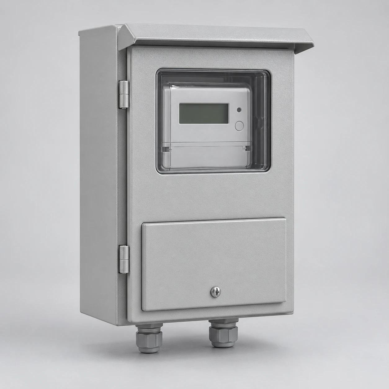
Our enclosure scope focuses on the specified housing and agreed hardware interfaces. We coordinate these with the meter or system provider, while platform operation and account services remain with the assigned operator.
Our enclosure work supports the meter and its users
The enclosure provides the mounting structure, equipment space and access around the selected meter. We consider how the meter is fixed, how its display is read and how the cable connections reach it.
For a new installation, the meter-system arrangement establishes these interfaces from the start. For an enclosure replacement, we compare the existing meter and accessory positions with the proposed housing. Smart or prepaid functions belong to the selected devices, while our box layout supports their physical installation, viewing and service access. This keeps the equipment discussion focused on the hardware your project uses.
We adapt the layout to integrated or split customer interfaces
Integrated interface
When the display or keypad is part of the meter, we coordinate its viewing and operating position with the enclosure door, window and access areas.
Split customer interface
A separate customer interface unit can be located away from the meter. That changes the device positions and connecting path, and can remove the need for a customer-operable opening at the meter enclosure.
Interface relationship: customer interface ↔ selected meter ↔ defined communications path ↔ system operator.
We use the selected system's arrangement to determine which devices share the box and which interfaces extend beyond it.
We coordinate the hardware around its installation role
We connect the physical component scope to the layout, with the meter provider and project team identifying the selected devices. The hardware schedule helps each interface remain clear as the enclosure develops.
| Hardware | Layout relationship |
|---|---|
| Enclosure and mounting board | Available fixing area, doors and access |
| Meter | Body envelope, terminals, display and sealing provisions |
| Customer interface | Integrated or remote location and connection path |
| Communication module | Fixings, supply interface and service access |
| Antenna and cable | Position, routing and enclosure penetration where required |
| Main or protective devices | Assigned compartment and electrical connections |
We define included components in the project scope alongside the hardware supplied by the assigned system partners.
Our enclosure layout follows the service and meter interfaces
We work from the service voltage, phase, conductors, frequency and metering method together with the meter's mounting or socket drawing. Direct-connected and instrument-transformer arrangements place different equipment and connection demands on the housing.
We coordinate the incoming and outgoing interfaces with any main disconnect or protective equipment included in the assembly. Our meter-main combinations content explains this relationship in more detail. The electronic features of the meter sit within that wider service arrangement, with its terminal, compartment and access requirements carried into the physical layout.
We bring the display, board and cable space together
The usable mounting area is shaped by the meter body, fixing centres, terminal covers and surrounding accessories. We coordinate these elements with the outside enclosure dimensions so the internal layout and installation footprint work together.
For a customer-facing display or keypad, reading angle and normal access influence its position. A remote customer interface instead needs its defined connection route and supply arrangement. We discuss these details with the meter provider before settling windows and openings, keeping the enclosure suited to the selected architecture and the way users interact with it.
Antenna placement connects radio performance with enclosure design
Metal around an antenna can reduce radio performance. We therefore consider enclosure material, antenna position and nearby metalwork with the selected device's installation requirements. An external antenna, where specified by the system design, also introduces a cable route and a sealed enclosure interface.
The device's protocol, frequency band, connector and antenna requirements are inputs to this coordination. We bring the physical mounting and routing details into the box drawing, while the system provider defines the required link behavior. Hardware and interface information are sufficient for this discussion; account credentials remain with the operator.
We coordinate materials, viewing access and sealed areas
Indoor and outdoor locations bring different combinations of moisture, sunlight, dust, corrosion and impact exposure. We consider the body material and finish with the door, viewing window, gasket and entry fittings, including any antenna penetration.
Windows serve the selected display position, seals connect adjoining surfaces and the mounting board supports the hardware arrangement. We also distinguish normal customer access from utility or operator access to protected areas. Our outdoor meter boxes and multi-meter enclosures content develops exposure and multiple-account layouts where those apply to the project.
Our interface documents keep the hardware configuration clear
We coordinate the enclosure general arrangement, meter mounting reference, component scope and connection interfaces with the selected system's information. Device identifiers and document revisions help relate each piece of hardware to its intended position.
Information for delivery and later changes
We connect the supplied hardware references and enclosure drawing to the agreed delivery documents. When a window, antenna fitting or other accessory changes, we discuss its effect on the corresponding interface. The system owner retains the controlled software configuration and versions, while our enclosure discussion follows the hardware details that affect fit, access and routing.
We align the physical interfaces with the expected operating behavior
The enclosure and system teams need a shared picture of how the selected equipment is expected to behave. We use those requirements to coordinate access, hardware placement and the interfaces relevant to the box.
| Scenario | Coordination focus |
|---|---|
| Normal communications | Required connection path and device access |
| Communication loss and return | Status indication and the system's expected recovery behavior |
| Power restoration | Restart state and accessible indications |
| Customer interaction | Display visibility and intended keypad or interface access |
| Authorized remote functions | Selected system behavior and operator-controlled permissions |
Project checks and their responsibilities are agreed around the selected system and our enclosure scope.
Discuss your smart or prepaid meter enclosure with us
Start with the meter model, installation location and whether the customer interface is integrated or separate. Add the planned accessories and quantity if known. We can then discuss the mounting board, access, cable routes and antenna arrangement with your team.
Meter handling and internal electrical service remain with authorized personnel; normal operation follows the selected system's user instructions. For our enclosure discussion, mention the available meter drawings and the hardware interfaces you want to coordinate. We can arrange the next information exchange from there.