
Motor Control Cabinets and MCC Configurations
We configure motor control cabinets around the motor and the equipment it drives. Pumps, fans, conveyors and other loads bring different starting and running demands, so we connect the control method with the power circuit, command interfaces and cabinet layout from the beginning.
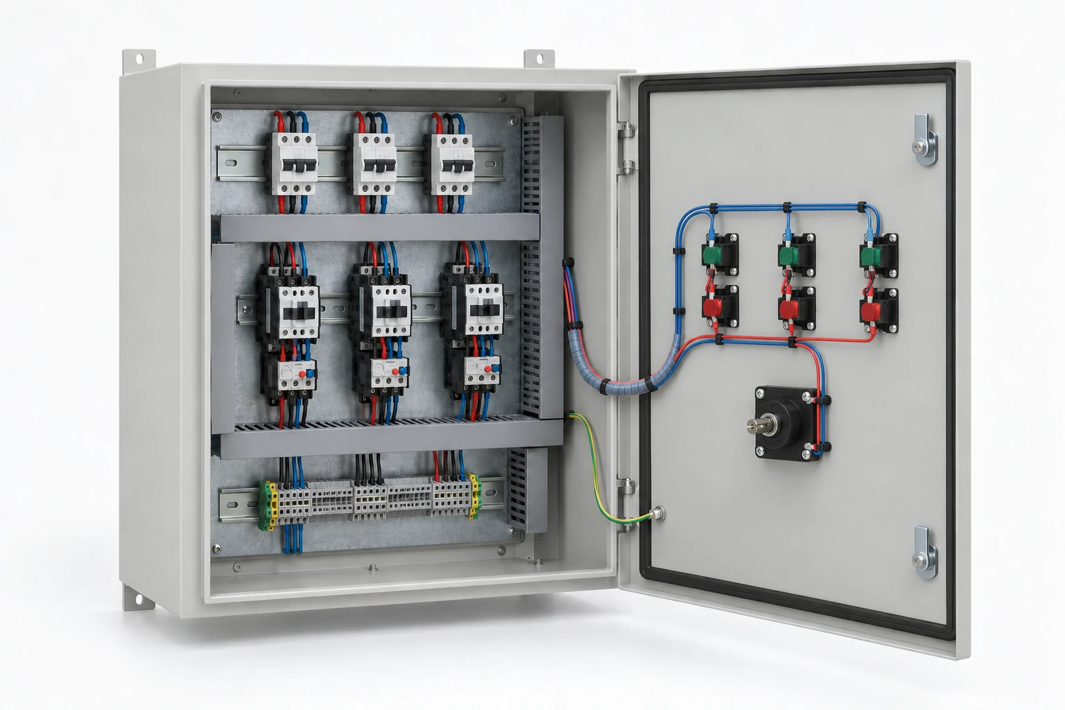
One motor or an organized group of motor feeders
A starter cabinet can serve a single motor or a small related group. A motor control center, or MCC, organizes multiple motor-control units around a common distribution structure. The difference affects incoming equipment, feeder grouping, control connections and service access as well as overall size.
We discuss the cabinet or multi-feeder arrangement against the operating process. Functional MCC path: incoming supply → common distribution → motor feeder units → motors and driven equipment. The selected assembly and equipment package are defined for the project. Grouping feeder information consistently helps the operating team connect each circuit with its motor and process function.
The motor and driven load define the starting point
| Operating detail | What it contributes | Configuration relationship |
|---|---|---|
| Motor nameplate | Voltage, frequency, current, power and duty | Electrical interface and device selection |
| Driven equipment | Load torque and inertia | Starting and acceleration needs |
| Operating cycle | Starts per hour and running duration | Repeated duty and thermal conditions |
| Speed and stopping | Speed range, stopping behavior and possible returned energy | Control method and drive interfaces |
A conveyor starting with material on it presents a different task from an unloaded start. We use these descriptions alongside the nameplate so the cabinet configuration follows the machine's work, including changes to duty in a replacement project.
Match starting behavior and running speed to the process
| Method | Main function | Application focus |
|---|---|---|
| Direct starting | Connects the motor for starting and fixed-speed operation | Starting current, available torque and source conditions |
| Reduced-voltage arrangement | Changes the starting voltage before normal running | Motor connection and load torque during acceleration |
| Soft starter | Controls the starting ramp and configured stopping functions | Acceleration, repetition and load behavior |
| Variable-frequency drive | Controls motor speed through its electrical output | Speed range, torque duty and motor compatibility |
We discuss the method from the required behavior. A controlled start and continuous speed adjustment are different needs, so a soft starter and a drive occupy different places in that conversation.
Starting sequences connect motor duty to the supply
Motor starting affects the supply at a different point from normal running. The upstream transformer, available source capacity and other operating loads all influence the conditions seen by a starting motor. We bring the expected sequence into the cabinet discussion with the site's electrical information.
Illustrative pump-group sequence
Staggered pump starts create a different demand from several pumps starting together. A standby pump starting while other pumps remain loaded adds another case. We use these scenarios to discuss feeder functions and command sequencing, keeping acceleration and permitted supply variation visible. A total motor-power figure alone cannot describe all three conditions.
Motor protection and assembly duty work together
Motor overload protection follows the motor and its duty, while short-circuit protection responds to a different electrical condition. Incoming equipment, feeder devices, conductors and motor-control components need to work as a coordinated assembly under the project's supply conditions.
We connect the cabinet equipment information with the responsible team's protection design. The selected device combinations and complete assembly rating remain associated with the actual feeder arrangement. Process commands and machine-safety functions are handled through their corresponding design roles. This keeps a normal start request, a protection trip and a safety-related action distinct when the control interface is developed.
The drive, motor and cable form an operating system
A drive configuration connects the motor model and speed range with the cable route, acceleration, deceleration and braking duty. Where the machine can return energy, that behavior also belongs in the power-interface discussion. We coordinate these requirements with the selected drive information and the machine team.
Motor drives and equipment AC sources
A variable-frequency drive is configured for a motor and its output interface. A general equipment AC frequency source is selected for a different supply task, including the connected equipment's waveform, neutral and load requirements. This distinction helps route a motor-speed project separately from powering a complete machine with mixed loads.
Commands, feedback and restart permissions
Start, stop, run feedback, trip and reset each describe a different control function. A speed-controlled motor adds a speed reference and relevant feedback. We organize these interfaces around the project's local stations, relay logic, PLC or supervisory system, with clear authority when modes change.
Fault reset clears a defined fault state; restart permission determines whether motion may resume. Keeping those actions separate helps the process team specify recovery after lost power or communication. Multi-motor sequences can then be coordinated with the automation system behavior, while each feeder retains identifiable commands and operating indications.
Arrange power equipment for heat removal and service
Power connections and enclosure construction
Busbar joints, terminal groups and cable approach connect the electrical duty with physical space. We discuss conductor and terminal compatibility together with enclosure material, finish and the installation environment. Cable bends and connection access remain part of the layout around the motor feeders.
Heat sources and equipment replacement
Starters, drives and auxiliary supplies contribute different losses across the operating cycle. Their placement influences ventilation routes and access to cooling components. We consider device removal space alongside normal observation and service needs. Future feeder positions and the electrical capacity to serve them are developed as separate expansion requirements.
Motor-feeder documents and project checks
We connect feeder identifiers, equipment details and the control sequence within the agreed project information. Operating-mode changes, interlock blocking, trip indication, stopping and power recovery provide useful scenarios for aligning the expected behavior with cabinet functions.
Inspection activities and records follow the selected equipment and agreed scope. Schematics, device references and any included parameter files remain tied to their revisions. Installation and checks on connected machinery are carried out by qualified project personnel under the machine's procedures. Clear labels and instructions help operators report the affected motor, indicated condition and operating state when attention is needed.
Discuss your motors and operating duty
Start with the motor list and what each motor drives. Tell us whether the process needs fixed speed, controlled acceleration or variable speed, and how often it starts. We can then discuss the feeder arrangement, supply interface and cabinet layout with your team.
As the configuration develops, we coordinate equipment identifiers, compatible replacement information and any included parameter references. Transport sections, packed dimensions and site access are discussed alongside quantity and destination. This keeps delivery and future replacement connected to the actual motor-control arrangement rather than to a generic cabinet size.