
Three-Phase Meter Boxes
We configure three-phase meter boxes for commercial buildings, workshops and other project applications. Our layout brings the service conductors, selected meter and cable routes together with the space needed for reading, connection and maintenance.
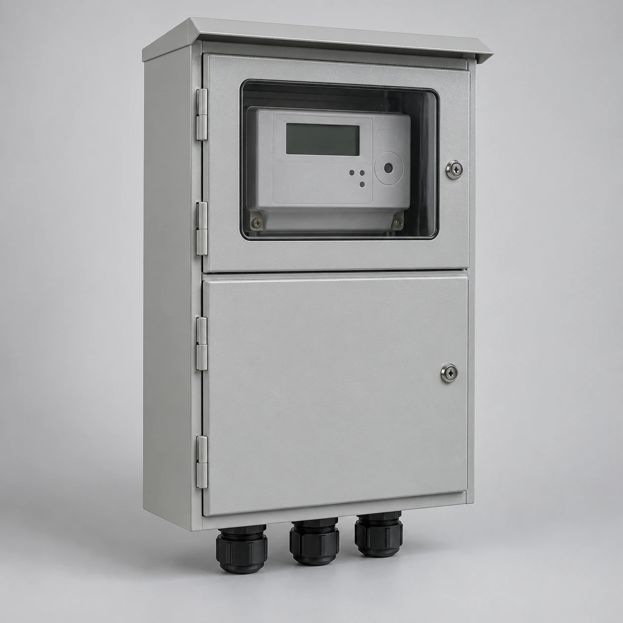
We coordinate the enclosure, mounting arrangement and selected components with the project service drawing. The agreed supply scope identifies the meter, socket, instruments and adjacent protective equipment.
Our three-phase layouts connect metering with the site
We begin with the function of the assembly: a housing for an identified meter, a socket-mounted arrangement or a cabinet combining metering with adjacent electrical equipment. That function determines the mounting area, internal divisions and connection interfaces.
For a building with several accounts, we also coordinate the relationship between each meter position and its outgoing supply. A multi-meter arrangement addresses those individual accounts, while a single account may still require separate metering and protective-device spaces. Our meter-box range brings these project choices together.
We translate the service arrangement into the layout
Three-phase services can have different conductor and voltage arrangements. We work from the project's actual service information so the meter interface, terminal areas and cable routes correspond to the same electrical system.
| Service factor | Design relationship | Our layout focus |
|---|---|---|
| Three- or four-wire arrangement | Conductor and neutral provisions | Terminal allocation and connection space |
| Wye or delta arrangement | The project's service and measurement connections | Alignment with the specified metering diagram |
| Voltage references | Line-to-line and line-to-neutral where applicable | Clear device and interface requirements |
| Frequency and duty | Electrical operating conditions | Coordination with the selected equipment |
The service drawing provides a common reference for our equipment layout and the project team's site connections.
Direct and CT metering create different space requirements
Direct-connected metering
The meter interface lies in the service-current path. We coordinate its mounting or socket arrangement with the main-current terminals, cable approach, cover clearance and sealing area.
Transformer-operated metering
Current transformers and the specified measurement connections introduce additional equipment and terminal space. We coordinate the instrument arrangement, meter compartment and test facilities defined for the project.
The choice follows the service and utility metering requirements rather than a universal current threshold. Our CT metering cabinets content develops the instrument and compartment relationships in greater detail.
We coordinate the components around the metering method
We use the selected method to organize both the equipment layout and its interfaces. This keeps the meter, measurement devices and adjacent main equipment connected to one configuration discussion.
| Configuration area | Direct-connected arrangement | Transformer-operated arrangement |
|---|---|---|
| Meter interface | Specified service-current meter or socket | Instrument-rated meter interface |
| Measurement equipment | Space around the main-current connections | CTs and other specified sensing interfaces |
| Test facilities | Provisions required for the selected meter | Specified measurement test interfaces |
| Access and sealing | Meter and connection covers | Instrument and meter areas |
| Main equipment | Included or adjacent assembly | Included or adjacent assembly |
Our mounting layout follows the selected meter
We coordinate the meter's outside envelope with its actual fixing and connection interface. For a board-mounted device, fixing centres and terminal-cover space determine how it sits on the board. For a socket-mounted device, the socket form, contacts and retention arrangement define the interface.
Ring or ringless construction and any specified bypass are handled within that configuration. We consider the door position and usable mounting area at the same time, so the meter and its terminals remain accessible within the finished box. The model drawing helps align those dimensions before fabrication.
We keep measurement and protection areas clearly organized
Our layout distinguishes the service-current path, measurement connections and neutral arrangement. We coordinate these with the project schematic and the upstream and downstream equipment, including the terminal boundary at each connection.
The main disconnect and protective devices have their own functions and space requirements. When they share the housing with the meter, we consider their placement, normal operating access and compartment boundaries together. Our meter-main combinations discussion covers this relationship between metering, main equipment and outgoing circuits.
We balance four kinds of space in the enclosure
| Space | What it accommodates |
|---|---|
| External envelope | Wall or support footprint and enclosure projection |
| Usable mounting area | Meter, socket, instruments and their fixings |
| Entry and termination area | Conductors, terminals and cable bends |
| Access envelope | Door movement, removable covers and authorized service |
We coordinate surface mounting with support and projection, or recessed mounting with the wall opening and finished surface. Nearby equipment and the reading position also shape the layout.
Material and terminal choices follow the environment
Enclosure construction
Metal construction provides mechanical support and works with a selected surface finish and bonding arrangement. Non-metallic construction offers an insulating structure, with material choice shaped by impact, temperature and sunlight exposure. We discuss these factors alongside the required mounting and access format.
Doors, entries and terminals
Doors, windows, seals and fittings form the enclosure around the equipment. We coordinate their placement with the cable route and installation environment. Fitted terminals are selected around conductor material, size range and connection requirements. Our outdoor meter boxes content considers external exposure in more detail.
Our documents connect the service diagram to the cabinet
We bring the meter reference, terminal arrangement, dimensions and access zones into the project drawing set. Component identifiers link the physical layout to the agreed equipment scope, while the drawing revision keeps subsequent changes understandable to both teams.
We coordinate the applicable dimensional, assembly and functional checks with the project requirements. Clear identification and agreed records support receiving and installation preparation. The serving utility's metering drawing remains the reference for its service interface, alongside our enclosure and assembly information.
We plan packing and identification for delivery
We consider meter openings, fitted devices, doors and terminal areas when discussing packing for the selected configuration. Package identifiers and the packing list help the receiving team connect delivered items and accessories to the order.
For follow-up questions, the equipment reference and final layout help us identify the relevant part or connection boundary. Authorized utility parties handle meters and sealed areas, while qualified personnel carry out electrical installation and internal service. Normal external observations can identify visible damage or a door issue for the appropriate project contact.
Discuss your three-phase metering project with us
Start with the service arrangement, selected meter or metering method, installation location and quantity. We can discuss the enclosure and mounting approach from those inputs, then work through the cable routes and project utility requirements together.
If a meter or CT arrangement is still being selected, let us know which interfaces are already defined. That helps us focus the next conversation on the layout decisions that matter for your project.