
ZFSBW Compensated Voltage Stabilizers
Our ZFSBW compensated voltage stabilizers help match a changing incoming supply to your equipment’s operating voltage. Explore 14 models from 10 to 400 kVA, then work with us on the input range, load behavior and installation arrangement for your project.
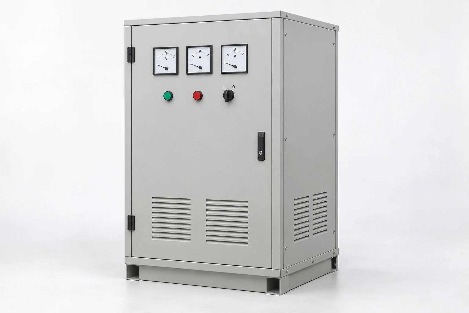
Explore our ZFSBW model range
Our ZFSBW range includes 14 models from 10 to 400 kVA. The table combines capacity, voltage designation, enclosure dimensions and weight to support your equipment selection. Each model inquiry includes the chosen identification and capacity, giving our team a clear starting point for the configuration discussion.
Connect the model to its operating duty
We consider the load and incoming-voltage conditions together. A machine with a steady running demand creates a different regulation task from a shared feeder with frequent motor starts. The closest capacity is therefore the beginning of selection; the operating description helps us develop the appropriate electrical and physical arrangement. You can also contact us about a capacity or installation requirement beyond the listed models.
| Model | Capacity (kVA) | Voltage | Enclosure dimensions (mm) | Weight (kg) | Inquiry |
|---|---|---|---|---|---|
| ZFSBW--10 | 10 | 380V | 350 × 500 × 470 | 40 | |
| ZFSBW--15 | 15 | 380V | 350 × 500 × 470 | 46 | |
| ZFSBW--20 | 20 | 380V | 380 × 500 × 700 | 90 | |
| ZFSBW--30 | 30 | 380V | 380 × 500 × 700 | 100 | |
| ZFSBW--40 | 40 | 380V | 450 × 600 × 820 | 120 | |
| ZFSBW--50 | 50 | 380V | 450 × 600 × 820 | 130 | |
| ZFSBW--60 | 60 | 380V | 450 × 600 × 820 | 146 | |
| ZFSBW--80 | 80 | 380V | 500 × 620 × 970 | 180 | |
| ZFSBW--100 | 100 | 380V | 600 × 980 × 1210 | 240 | |
| ZFSBW--120 | 120 | 380V | 600 × 980 × 1210 | 260 | |
| ZFSBW--150 | 150 | 380V | 650 × 1030 × 1260 | 305 | |
| ZFSBW--200 | 200 | 380V | 700 × 1030 × 1310 | 370 | |
| ZFSBW--250 | 250 | 380V | 700 × 1030 × 1310 | 415 | |
| ZFSBW--400 | 400 | 380V | 800 × 1100 × 1700 | 644 |
No matching model. Clear the search or describe your required capacity in an inquiry.
How our voltage compensation addresses supply variation
Our ZFSBW series uses voltage compensation to adjust the voltage delivered to the load. A corrective voltage is added to or subtracted from the incoming supply: supporting the output when the supply falls and reducing the output when the supply rises, within the selected operating range. This connects regulation to the changing supply condition.
Define the regulation around the application
We discuss the sensing, control and regulating arrangement with the chosen construction and duty. The required correction range, frequency of supply changes and maintenance access help shape that discussion. Compensation describes an electrical function, while cooling describes how the construction handles heat. Our ZFLS oil-immersed stabilizers bring a further construction option into the wider regulation range.
Understand the incoming voltage at your equipment
We use voltage observations from the intended connection point to understand the operating problem. Normal variation across a working shift, a drop during a machine start and a short disturbance can affect equipment differently. The value, duration and load state help us connect each event to the regulation requirement.
Give each reading useful context
A record showing the phase or phase pair, time, measured voltage and equipment operating at that moment is especially helpful. Frequency, neutral arrangement and the measurement location complete the picture. Your qualified site team can obtain these readings safely. We use them to discuss the input window and correction duty, while brief interruptions or other power-quality issues are considered separately from sustained voltage regulation.
Define steady output and dynamic recovery
We align the desired output with the connected equipment's operating tolerance. The model table carries the 380V designation; our project schedule defines its voltage role and measurement basis together with the required input range, output target and frequency.
| Parameter | Meaning for your equipment |
|---|---|
| Input range | The supply limits and voltage basis used for the configuration |
| Steady output tolerance | The permitted output variation after the regulating process has settled |
| Response start | When correction begins following a defined input or load change |
| Recovery to tolerance | When the output returns to and remains within the specified band |
| Operating capacity | The supported load across the agreed input and phase conditions |
We keep these conditions together when discussing performance. A quick start to correction and a quick return within tolerance describe different parts of the response; the size of the voltage or load change also matters.
Size for the load at the lowest operating input
We consider running kVA, power factor, starting demand and repeated load changes when discussing capacity. At a given output power, lower incoming voltage generally requires more input current. That relationship makes the lowest operating input a useful condition for reviewing current, correction duty and heat, alongside the nominal capacity.
One machine or a shared feeder
For a machine supply, its nameplate and operating cycle show the running and starting requirements. For a shared feeder, we discuss simultaneous demand, phase allocation and which loads change together. Rectifiers and drives can introduce nonsinusoidal current that affects thermal loading. We use this detail to connect the selected stabilizer with the actual duty instead of sizing only from a combined equipment power total.
Coordinate protection, bypass and recovery with the system
We discuss the required behavior during input outside range, overload, phase faults and internal alarms as part of the system configuration. Your operating priorities help define the response and any required indication or remote-status interface. These functions are coordinated with the selected controls and upstream and downstream protection.
Plan the bypass function where the project requires it
Where a bypass is specified, we define its electrical path, interlocking and effect on regulation with the installation design. A direct bypass connects the load to the available supply, so its use needs to fit the equipment's voltage tolerance. Qualified personnel carry out bypass switching and fault work under the selected unit's instructions and site procedures. Recovery and reset behavior are included in that operating arrangement.
Bring materials, insulation and cooling into the design
We consider winding conductors, magnetic components and insulation together with the load and regulation duty. Copper and aluminum differ in conductivity and density; conductor dimensions, joints and terminal interfaces turn those material properties into the working assembly. Core design influences magnetic loss, while winding resistance contributes to heating under load.
Make thermal management and service access practical
Insulation, component spacing and ventilation influence the path from generated heat to the surrounding air. We discuss ambient temperature, dust and enclosure placement when coordinating cooling. Access to the fitted regulating, control and cooling components also matters for inspection and maintenance. The selected construction determines the relevant parts and care instructions, keeping service planning connected to the equipment you receive.
Fit the stabilizer into your electrical room
We use table dimensions and weight for initial space planning, then coordinate the general arrangement with your installation. Labeled dimension directions, mounting positions, terminal access and cable-entry routes bring the model into the actual room or production layout.
Allow space for cables, airflow and handling
Door movement, cable bending and ventilation need room around the equipment outline. We discuss these details together with the path from unloading to the final position. Equipment and packed shipping weights support different parts of that planning, while packing dimensions and handling provisions help your receiving team prepare. Keeping the access route and service space clear also makes later inspection and component replacement more practical.
Our production and ZFSBW project documents
We have annual production capacity of 3,000 voltage stabilizers. Our manufacturing resources include foil and wire winding equipment, vacuum-pressure impregnation equipment and high-temperature ovens. These capabilities support winding and insulation processing for the agreed equipment construction.
Our high-current load platform, high-power AC test supplies and temperature monitoring equipment support production and project checks. We agree the relevant voltage-regulation, load-response and thermal checks with the selected configuration and operating requirements.
Connect production, delivery and continued operation
We coordinate the electrical schedule, connection and outline drawings, nameplate details, agreed records and packing information with the order. Model identification and the final documentation give the receiving and commissioning teams a common reference. During service, the operating condition and any alarm information help us discuss an inquiry in the context of the installed configuration.
Discuss your ZFSBW requirement with us
Choose a model in the table or describe the equipment and capacity you need to supply. A short summary of the incoming-voltage variation, load behavior and required output gives us a useful starting point. Include the quantity, destination and available installation space as the discussion develops.
If you have voltage records, a machine nameplate or an electrical drawing, mention them so we can arrange a document exchange. Tell us about any required bypass, alarms or status connections. Our voltage stabilizer range provides more application context, and we can work through the configuration with your project team.