
Autotransformers for Industrial Voltage Matching
Our autotransformers match industrial supply and equipment voltages where a shared electrical connection suits the installation. We develop the winding and connection arrangement around the required voltage relationship, load duty and available space, with our ZFSO three-phase series providing capacities from 3 to 500 kVA.
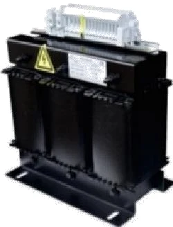
Choose shared windings where the system allows them
Our autotransformer configurations serve voltage-matching applications that permit electrical continuity between supply and load. That continuity is a defining feature of the product. Where the machine or project requires separate primary and secondary circuits, our isolation transformers provide the appropriate architecture to explore.
We discuss phase and wire arrangements, neutral requirements and the equipment's grounding interface with the project team early. This establishes a consistent basis for the winding arrangement and surrounding cabinet design. For a replacement project, the existing transformer diagram and machine information help distinguish a straightforward replacement from a change in system architecture.
Define source voltage, load voltage and current together
Step-up and step-down configurations
The source-to-load relationship sets the operating duty. We work from the actual supply voltage, required equipment voltage and their variation, then coordinate the connection arrangement and load capacity. Line-to-line and line-to-neutral values are identified explicitly where both appear in the project.
Voltage and current requirements move together: different connection points can carry different currents. A change in conversion direction therefore needs the corresponding connection and current review; a voltage pair alone is not authorization to reverse-feed the transformer. The selected diagram and nameplate keep the intended source, load and terminal arrangement clear for the installation team.
Select the power function your equipment needs
| Requirement | Equipment function |
|---|---|
| Match one nominal voltage to another | Fixed-ratio autotransformer where shared windings suit the system |
| Keep output near a target as input varies | Automatic voltage stabilization |
| Supply a different AC frequency | AC frequency conversion |
A fixed ratio follows changes in source voltage rather than automatically correcting them, and a passive transformer retains the source frequency. Where a project needs connection taps or an adjustment function, we discuss that requirement as part of its configuration.
Connect capacity selection to the operating sequence
We examine the machine's continuous demand alongside starting and intermittent loads. Motor starts, rectifier inputs and uneven phase loading affect the electrical and thermal duty differently. The load schedule helps us understand which equipment runs together and which events place the largest demand on the source.
The upstream power interface
Source characteristics, energization behavior and transformer impedance inform the project designer's protection coordination. We connect those considerations to the machine's permissible supply variation and installation arrangement. The transformer integration guide develops the wider machine interface, including auxiliary loads and cabinet space, so voltage conversion remains part of a coherent power arrangement.
Balance conductor, core and thermal requirements
The shared winding's material advantage is only one part of the design. Core construction affects the magnetic path and no-load loss, while winding resistance contributes load-related heating. We consider the selected conductor and insulation alongside these losses and the cooling available at the installation.
Copper, aluminum and terminal interfaces
Copper and aluminum designs use different cross-sections and connection arrangements. Their comparison includes winding space, mass, terminal compatibility and temperature behavior. Insulation thermal classification, operating temperature rise and ambient temperature are related but distinct requirements. In a cabinet, ventilation paths and nearby heat-producing components also influence the useful installation envelope.
Explore our ZFSO three-phase series
Our ZFSO three-phase series spans 3–500 kVA across 23 models. The ZFSO model table presents the capacity range, 380 V/220 V voltage designation, enclosure dimensions and weight. It offers a practical starting point for comparing capacity and the physical space available in a project.
We develop the source and load arrangement, frequency and terminal details with the selected application. A clear configuration also helps coordinate enclosure placement: cable approach, ventilation and access for replacing the unit can require space beyond the transformer outline. These details become especially useful when updating an existing machine with a fixed cabinet envelope.
Our manufacturing and configuration documents
Our production capabilities include wire and foil winding, vacuum pressure impregnation and high-temperature ovens. They support the manufacture of winding and insulation assemblies around the selected transformer design. Core-loss and interturn testing, load equipment and temperature monitoring support our technical and production work.
For the project, we bring the connection diagram, terminal identification, general arrangement and nameplate information into a consistent document set. Agreed inspection items and records follow the selected configuration. Keeping the drawing revision connected to the equipment identifier gives the machine builder, cabinet team and receiving staff a common reference throughout integration.
Coordinate handling and installation access
We discuss the mounting arrangement, lifting and handling information, packing and delivery interface as the equipment configuration develops. Net equipment mass and packed shipping mass serve different planning purposes, while packed dimensions help the logistics team assess access and transport arrangements.
Qualified personnel install and commission the transformer using its project documents. Practical service access allows inspection of condition and cooling paths without dismantling unrelated cabinet equipment. Retaining the nameplate information and current connection drawing also helps later maintenance planning, particularly where a replacement must fit existing mounting points and cable routes.
Discuss your voltage-matching project
Start with the available supply, the voltage your equipment requires and its load capacity or nameplate. Add the operating frequency and application, and we can work through the winding arrangement, loading pattern and installation conditions with your team.
For a replacement, an existing drawing or photograph of the equipment identification helps establish the starting configuration. For a new machine, tell us about available space, enclosure needs, quantity and destination. We use this information to develop a project-specific discussion of electrical connections, construction and the documents needed for integration.