
Prefabricated Substation Configurations
Our transformer and cabinet work supports prefabricated substation projects through coordinated equipment interfaces. We work with your team on voltage requirements, compartment layouts, heat removal and site access, connecting the electrical arrangement with the physical installation.
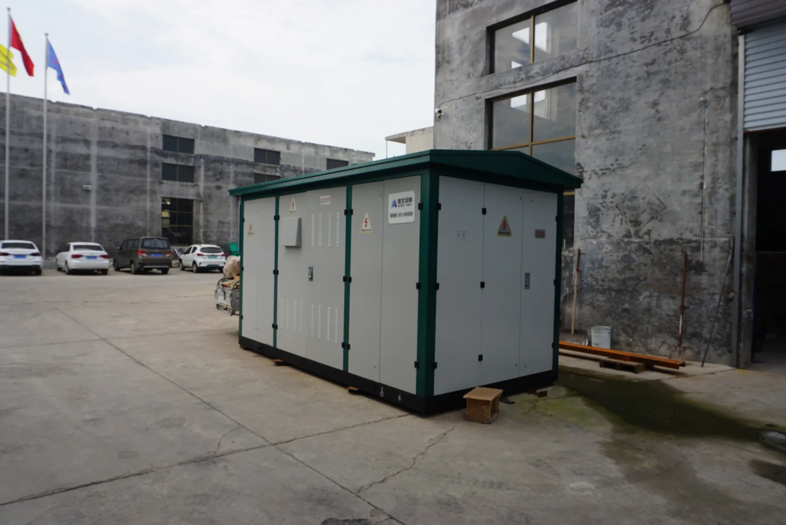
Bringing the equipment arrangement together
A prefabricated substation combines switching, transformation and distribution within a coordinated installation. The enclosure gives those functions their physical space; the electrical equipment connects the incoming network to the outgoing loads. Auxiliary power, metering and monitoring add further interfaces that belong in the same project discussion.
Equipment package and site connection
We use the one-line diagram and site layout to organize the transformer and cabinet requirements with your team. The quotation defines the selected equipment package and its interfaces with project-supplied items. This gives the enclosure, internal arrangement and site connection a shared starting point before dimensional decisions become fixed.
Connect incoming power to the outgoing loads
| Area | Function | Configuration inputs |
|---|---|---|
| Incoming network | Receives and switches the source supply | Voltage class, connection arrangement and fault duty |
| Transformer | Connects the required voltage levels | Load profile, winding arrangement and cooling |
| Outgoing distribution | Supplies identified load groups | Feeder demand, protection and future circuits |
| Auxiliaries | Support control, measurement and communications | Power sources, signals and cable interfaces |
We discuss these connections together because a change on one side can affect the rest of the arrangement. Frequency, phases and voltage references follow the actual project. Utility connection conditions and the site's electrical design establish the incoming-network requirements.
Walk-in and externally operated layouts
Operating access changes the footprint and the way equipment can be maintained. A walk-in layout includes an internal personnel area. An externally operated arrangement places the intended operating access at the enclosure exterior. We compare these approaches against the available site space and the equipment access needs.
| Consideration | Walk-in layout | External operation |
|---|---|---|
| Access space | Internal aisle and entry arrangement | Clear areas outside operating doors |
| Compartment layout | Equipment faces an internal access zone | Access is organized around the exterior faces |
| Replacement route | Doorways and internal movement space | External removal and lifting access |
Door movement, restricted areas and removal routes are developed with the operating team; the layout name alone does not determine an operating procedure.
The transformer and its enclosure work as a system
Continuous demand, peak loading and expansion plans shape the transformer requirement. Voltage class, winding connection and impedance also connect directly to the incoming equipment and outgoing distribution. We organize the transformer discussion around those duties, rather than starting with an enclosure size.
Loading and heat inside the package
Transformer losses contribute heat to the enclosure, so ambient conditions, cooling access and nearby auxiliary equipment belong in the same assessment. An enclosed installation can have a different heat path from open placement. For low-voltage conversion applications, our isolation-transformer family provides the corresponding product route; a medium-voltage station requires a transformer selected for its own voltage class and system duty.
Switching, measurement and automation interfaces
The one-line diagram places incoming devices, bus sections, transformer connections and outgoing feeders in their operating relationship. We use that arrangement to coordinate equipment spaces and interfaces with your switching and protection team. Alternate sources or bus ties also introduce operating states that must be reflected in the project design.
Switchgear configuration links the circuit arrangement to the chosen switching structure. Metering adds measurement points, equipment access and cable routes. Substation automation connects selected status, alarm and command signals to the supervisory system. Keeping these interfaces visible helps each equipment team use the same circuit and compartment identifiers.
Compartment construction and heat removal
Material and finish choices
Outdoor exposure combines moisture, sunlight, contamination and temperature changes. We discuss enclosure substrate, finish, roof, doors and sealing as a connected construction choice. Coated steel relies on the selected finish and its care; stainless steel selection also depends on the actual corrosive environment. Material choices are matched to the site rather than to appearance alone.
Ventilation and compartment layout
Heat needs a defined route from the installed equipment to the surroundings. Louvers, filters or other cooling arrangements affect airflow, sealing and maintenance access. Partitions influence both equipment separation and the heat path. We include access to cooling components in the layout so inspection and cleaning remain practical after installation.
Coordinate foundations, cable openings and access
The physical interface starts at the equipment supports. Foundation dimensions, support points, loads and cable openings need to relate to the same arrangement drawing. We discuss these dimensions with the project team while the site's civil designer develops foundations, drainage and surrounding levels.
Cable entries also need room for the chosen terminations and permitted cable bends. A small shift in an opening can affect the route inside the compartment, so entrance direction and equipment position are considered together. Space outside the enclosure serves unloading, operation and eventual replacement as well as the initial installation. Keeping those routes clear in the layout helps the site team plan work before equipment arrives.
Project information that connects equipment and site
We organize the agreed equipment information around the project one-line and general arrangement. Connection references, terminal schedules, component descriptions and equipment identifiers connect the electrical plan to the physical package. Together, these records help the customer coordinate interfaces among transformer, cabinet and other project equipment.
The inspection and document schedule is agreed for the selected package, including the relevant functional checks and operating information. Project standards and utility conditions are incorporated through the responsible design team. Clear revision control keeps accepted changes connected to the equipment drawings, giving installation and maintenance teams a useful final reference without obscuring which items belong to site work.
Plan shipping sections around the site route
The route from delivery point to foundation can influence the package as much as the operating footprint. Doorways, access roads, unloading areas and lifting positions determine what can be moved into place. We discuss those constraints before finalizing the transport arrangement for our agreed equipment.
Where shipping sections are used, each needs clear identification, packing dimensions, mass and handling information. The site team also needs to understand the interfaces between sections and the work required after arrival. Equipment protection during storage, receiving observations and field connection information are coordinated with the delivery plan. Professional installation and commissioning then follow the final project documents.
Discuss your substation project requirements
Begin with the incoming and outgoing voltage, expected load and a short description of the site. We can then discuss transformer and cabinet interfaces, access layout and the equipment arrangement with your team. A preliminary one-line or site sketch is helpful when available; it can be exchanged during the project discussion.
Operating access, visible indications and service space remain part of that conversation. Routine external observations can identify blocked access, damage or displayed alarms, while restricted compartments and electrical work remain under the authorized operating procedures. Quantity, destination and transport constraints can be developed alongside the configuration.