Our Power Equipment, Electrical Cabinets and Meter Boxes
Explore our five product families and the electrical interfaces around them. We connect voltage conversion, regulation, AC supply, cabinets and metering with the needs of your equipment and installation.
Search 44 product, configuration and model-series entries: 38 product and interface topics plus our six model ranges. A series or model search opens the relevant series page, where you can compare its model table and configuration details.
No matching topic. Try a broader term or
Find the equipment function your project needs
Our products address different parts of the path from incoming supply to connected equipment. Some change voltage or frequency; others organize protection, control and measurement. We use these functions to build a clear picture of the equipment your project needs, including where several products work together.
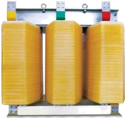
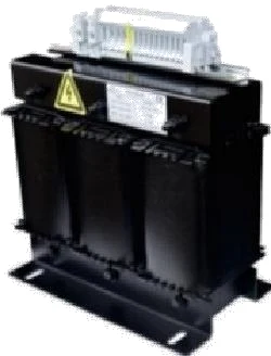
Our transformers for voltage matching and isolation
Our transformer range covers separate-winding isolation, shared-winding voltage conversion and control-circuit power. We select the winding approach around the electrical relationship you need between the supply and load. Capacity then follows the operating demand, including continuous load and starting conditions.
We offer single-phase and three-phase isolation transformers for industrial voltage matching and electrical separation. We combine load requirements, winding construction and installation conditions to develop the configuration, from a machine-mounted transformer to a unit integrated into a power cabinet.
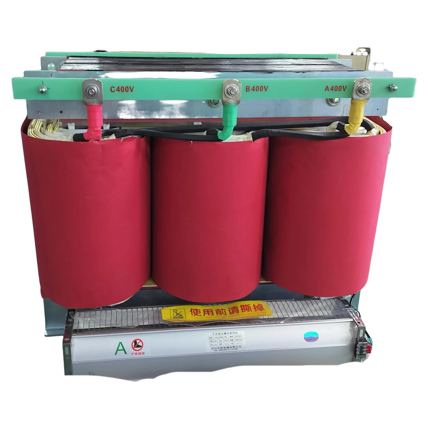
Our autotransformers match industrial supply and equipment voltages where a shared electrical connection suits the installation. We develop the winding and connection arrangement around the required voltage relationship, load duty and available space, with our ZFSO three-phase series providing capacities from 3 to 500 kVA.
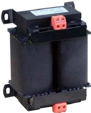
We configure control transformers for AC auxiliary circuits serving contactors, relays, solenoids and other machine controls. We bring together the required control voltage, continuous demand and short coil-pickup events, then coordinate the transformer with the available panel space and thermal conditions.
Our ZFSG three-phase isolation transformers span 5–500 kVA across 21 models. Choose a capacity for your application, then work with us on the input and output configuration, load conditions and installation layout.
Our ZFSO series includes 23 three-phase autotransformer models from 3 to 500 kVA. We connect shared-winding voltage conversion with your machine supply, operating load and installation space, helping you select a practical interface between the incoming power and your equipment.
Our voltage stabilizers for changing supply conditions
Our voltage stabilizers regulate the output as incoming voltage changes, helping match the supply conditions to the connected equipment. We consider the measured input variation, load demand and operating cycle together; a large starting load creates a different discussion from a steady continuous load.
Explore ZFSBW compensated stabilizers and ZFLS oil-immersed stabilizers. Their model ranges connect electrical capacity with the physical equipment. Cooling arrangement, installation environment and access for maintenance are also part of choosing the configuration.
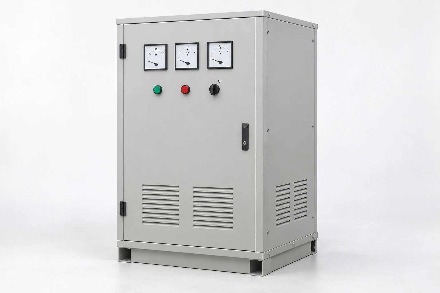
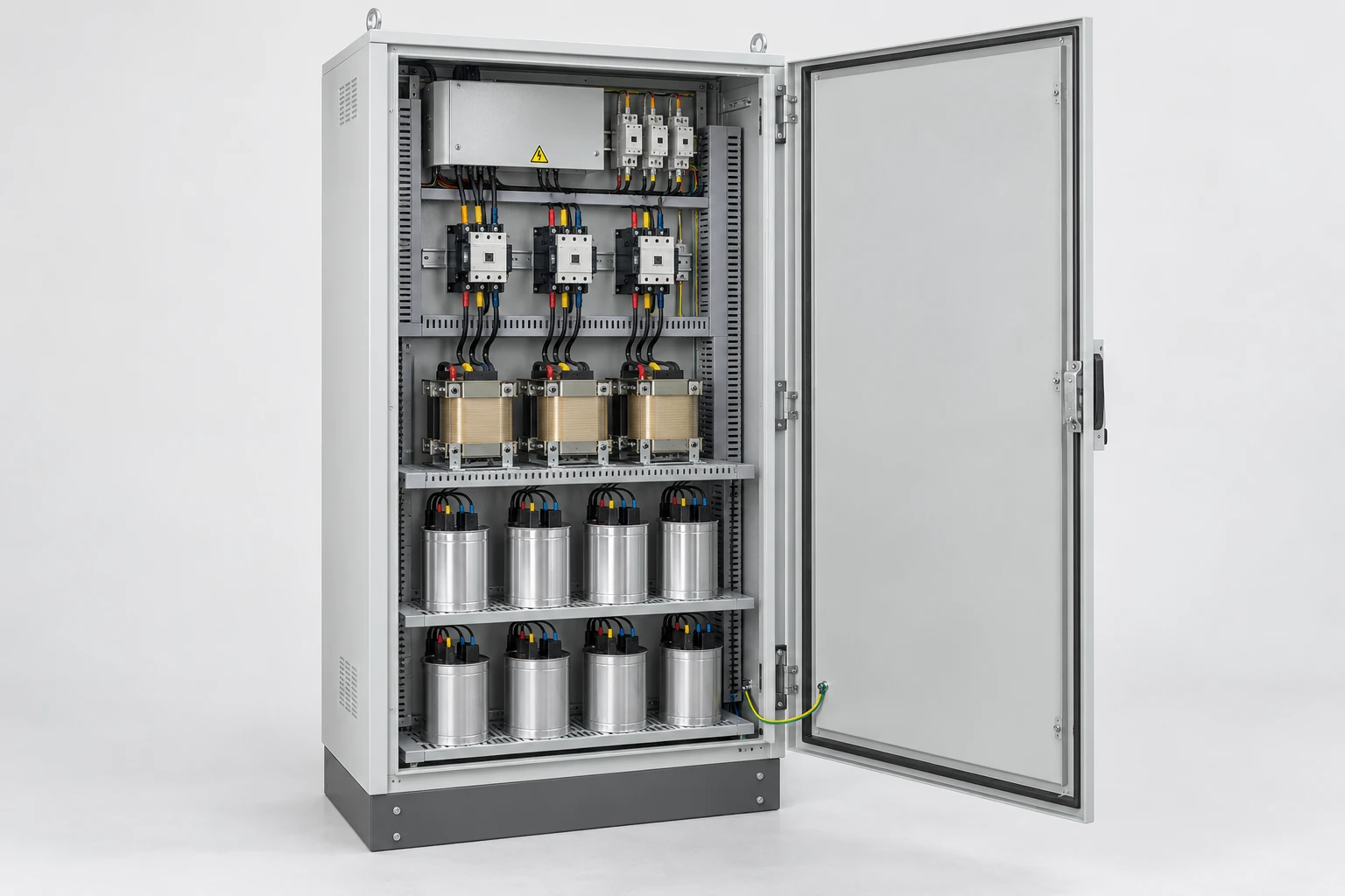
Illustrative configuration: a three-phase stabilizer cabinet. We define the equipment arrangement for your application.
Our industrial AC voltage stabilizers help match changing supply conditions to the voltage requirements of production equipment. We configure the regulation requirement around the input range, connected load and operating cycle, with our ZFSBW compensated and ZFLS oil-immersed series offering starting points for the project.
Our ZFSBW compensated voltage stabilizers help match a changing incoming supply to your equipment’s operating voltage. Explore 14 models from 10 to 400 kVA, then work with us on the input range, load behavior and installation arrangement for your project.
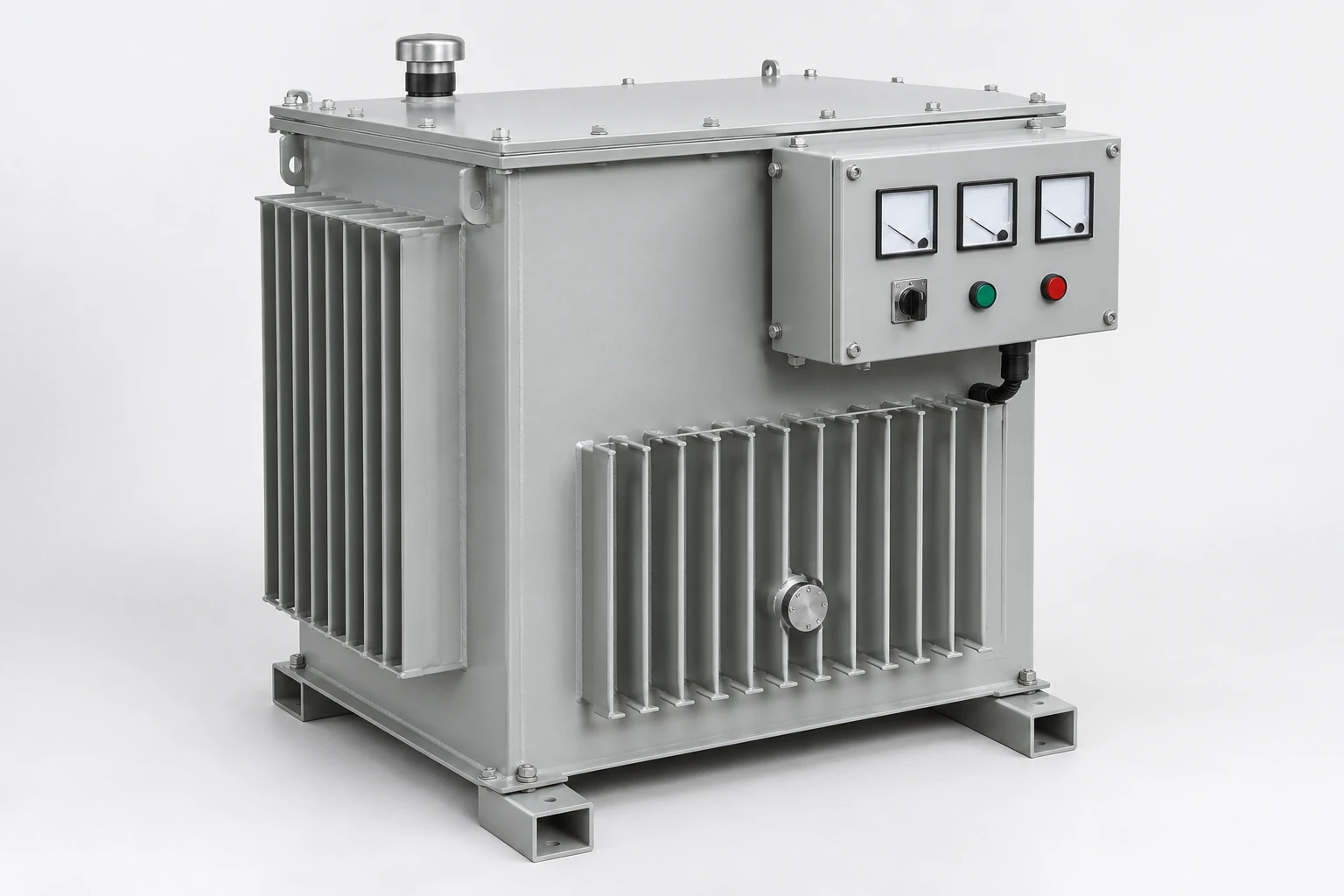
Our ZFLS oil-immersed induction voltage stabilizers combine brushless, contactless regulation with oil cooling. The 16-model range covers 100–3,000 kVA for projects that need coordinated voltage regulation, thermal design and installation planning.
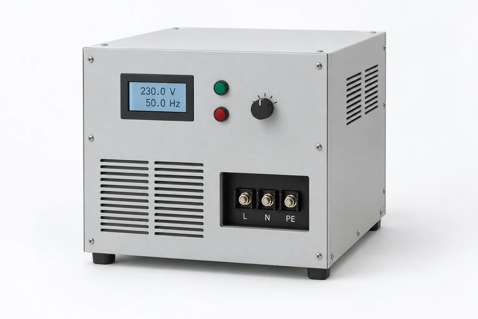
Our AC power supplies serve applications that need a defined output voltage and frequency, including equipment operation and electrical testing. We discuss the continuous operating points, startup demand and test transitions so the power source can be considered against the actual load behavior.
Single- and three-phase output
ZFDP single-phase and ZFSP three-phase ranges address different output arrangements. Input and output are separate configuration choices. For testing, the current demand and duration at each operating point are as useful as the overall power rating.
Our AC frequency power supplies serve equipment that needs a defined voltage and frequency relationship to the available supply. We work with export-equipment, production and testing teams to develop the output requirements, load capability and installation arrangement around our ZFDP and ZFSP product families.
Our ZFDP range provides single-phase AC output for equipment supply and testing applications. Explore 11 models from 500 VA to 45 kVA, then discuss the voltage, frequency and load conditions your equipment needs.
Our ZFSP three-phase AC power sources cover 11 models from 3 to 150 kVA. We connect model selection to your output voltage and frequency points, per-phase loads and the operating process of the equipment being supplied.
Power-supply cabinets with coordinated internal layouts
Our power-supply cabinet discussions bring conversion equipment, incoming protection and outgoing distribution into one physical arrangement. The internal layout needs room for wiring and thermal management as well as the power components themselves.
We work through the required AC or DC outputs, load groups, monitoring and access points with your project team. Cable-entry direction, mounting positions and door-mounted devices connect the cabinet to the surrounding installation. This approach keeps the mechanical enclosure and the electrical function developed together, whether the project concerns an enclosure or a fitted assembly.
Open cabinet layouts provide access to internal equipment, mounting areas and cable routes.
Our power supply cabinets bring power-conversion equipment, protection, distribution and controls into a coordinated layout. We start with the power your equipment needs, then work through the electrical interfaces, cabinet construction and access that make the configuration practical to install and maintain.
Cabinet and power interfaces within substations and switchgear
Substation and switchgear projects connect incoming power, transformation, switching and downstream distribution. Our related application content explains these interfaces so our cabinet and power-equipment discussion fits the wider electrical arrangement.
Voltage level, switching duty and fault conditions shape the equipment around each connection. Fixed and withdrawable constructions also create different access and maintenance arrangements. We discuss the relevant power and cabinet interfaces with the project team, using the one-line diagram to keep the network, transformer and outgoing circuits connected in the design conversation.
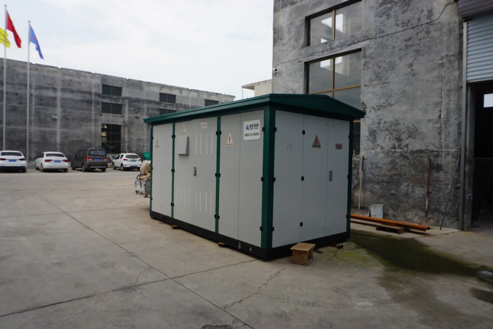
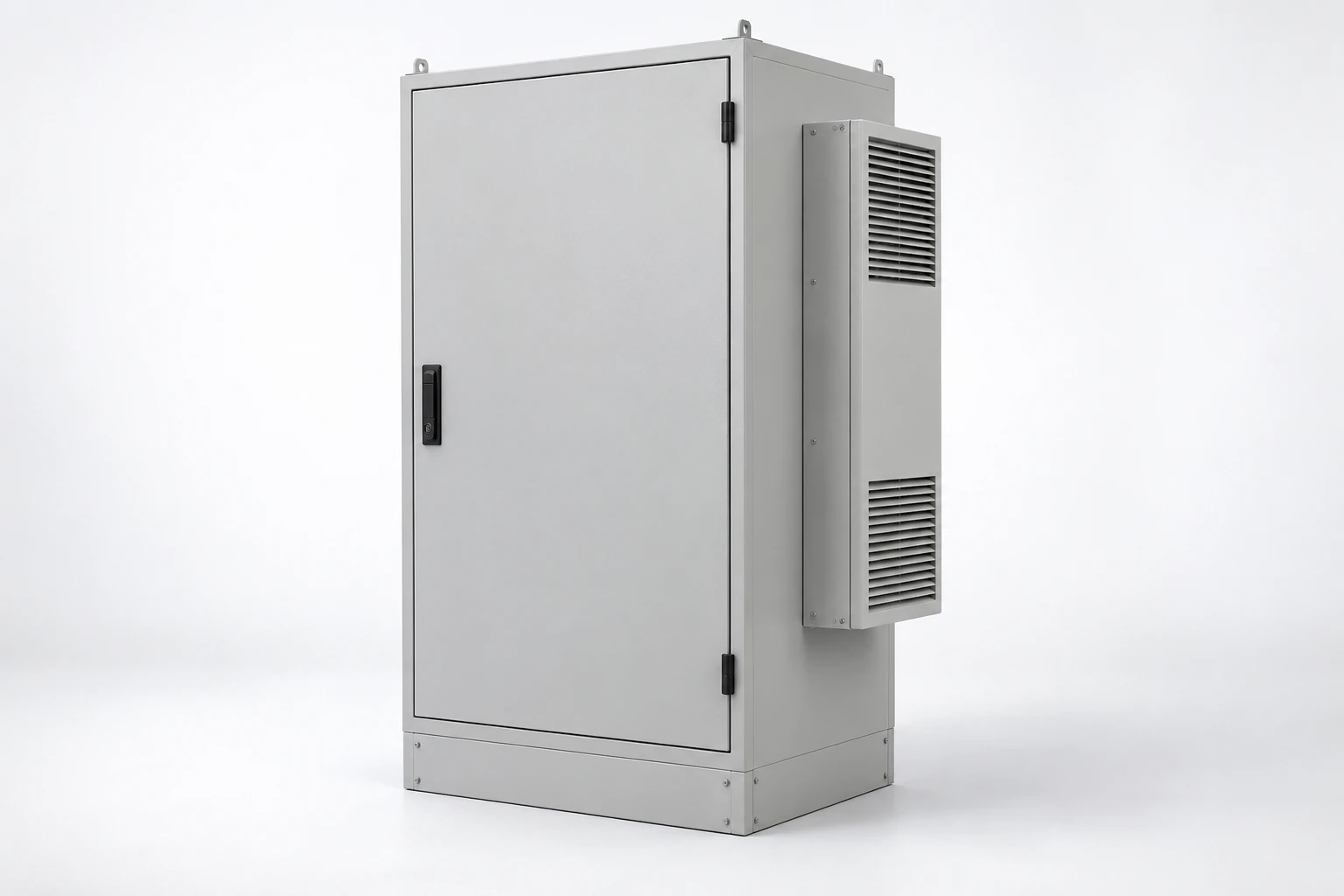
A multi-compartment outdoor enclosure provides separate access points for different equipment areas.
Our transformer and cabinet work supports prefabricated substation projects through coordinated equipment interfaces. We work with your team on voltage requirements, compartment layouts, heat removal and site access, connecting the electrical arrangement with the physical installation.
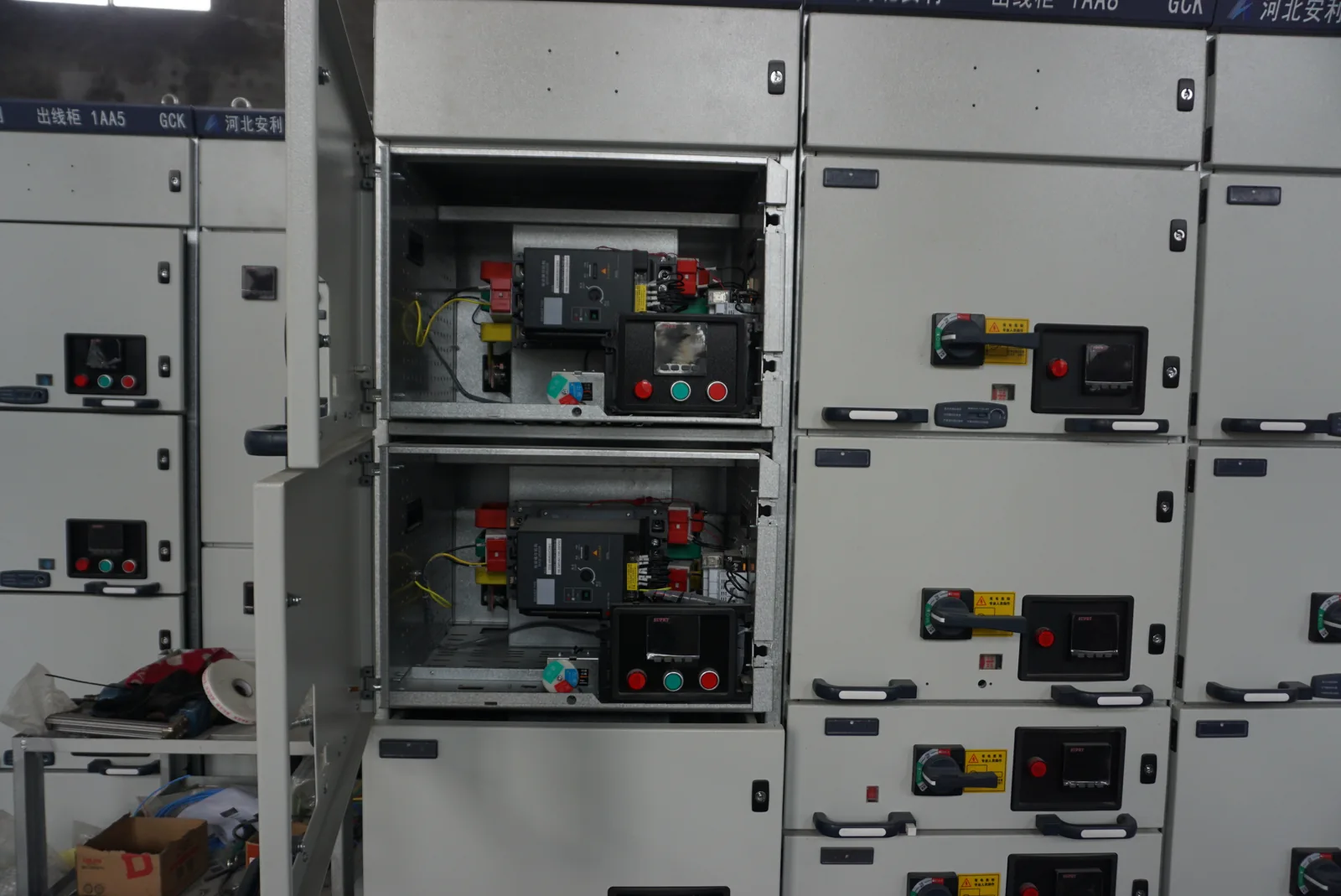
We develop cabinet configurations around your circuit duty and access requirements. For switchgear projects, that means considering switching structures, busbars, terminals and controls together, so the arrangement supports both the electrical system and the planned approach to maintenance.
Power distribution, compensation and rack connections
Our distribution cabinets organize incoming power and outgoing circuits around the connected loads. Circuit grouping, device placement and cable routes affect how the assembly is wired, operated and maintained. We consider room for later equipment alongside the electrical capacity available for it.
Reactive-power compensation and rack distribution introduce additional interface choices. Compensation depends on the load's reactive demand and harmonic conditions; a rack arrangement depends on inlet capacity, outlet groups and how loads behave if one supply path is unavailable. These topics help us discuss the appropriate cabinet and connection arrangement for your project.
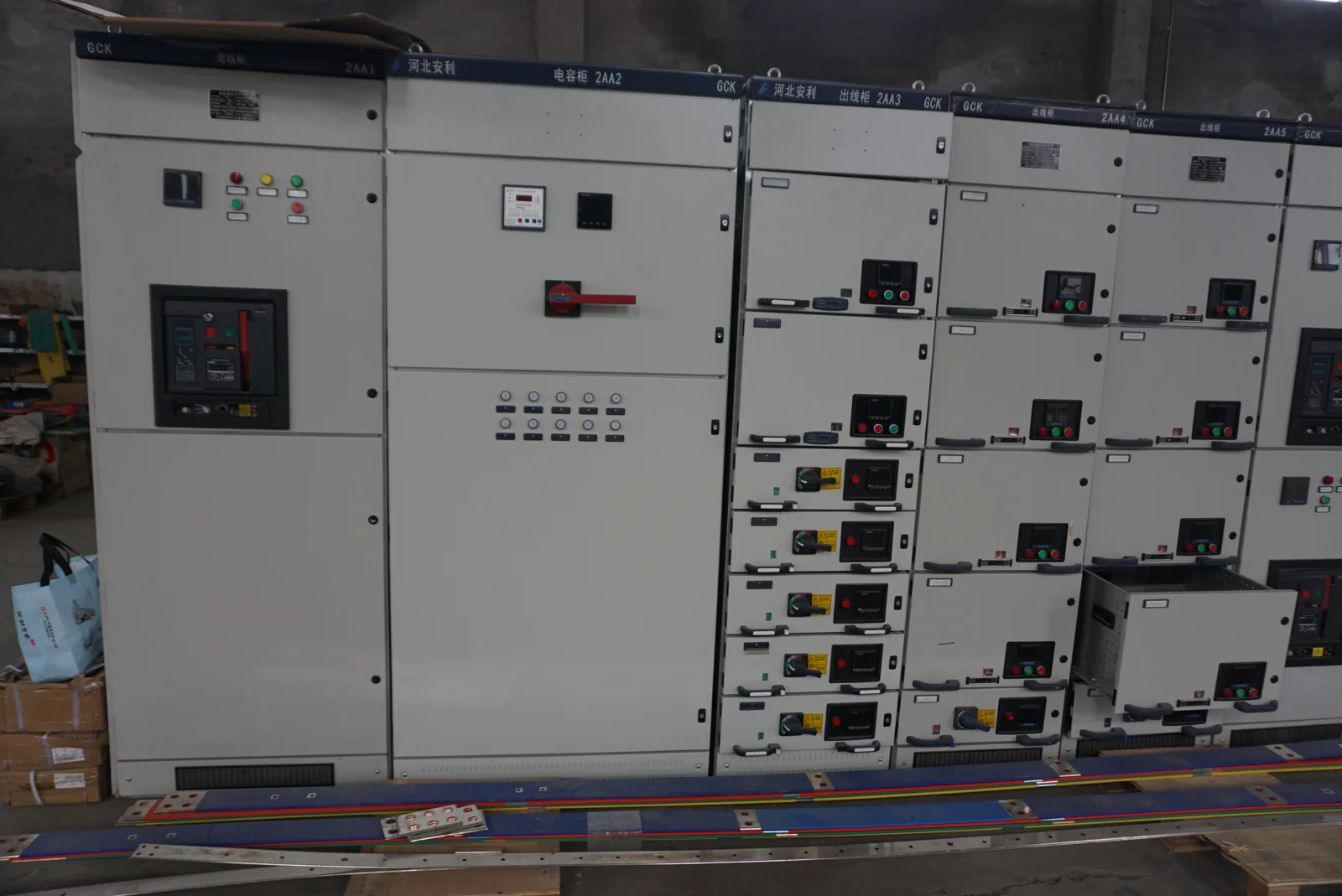
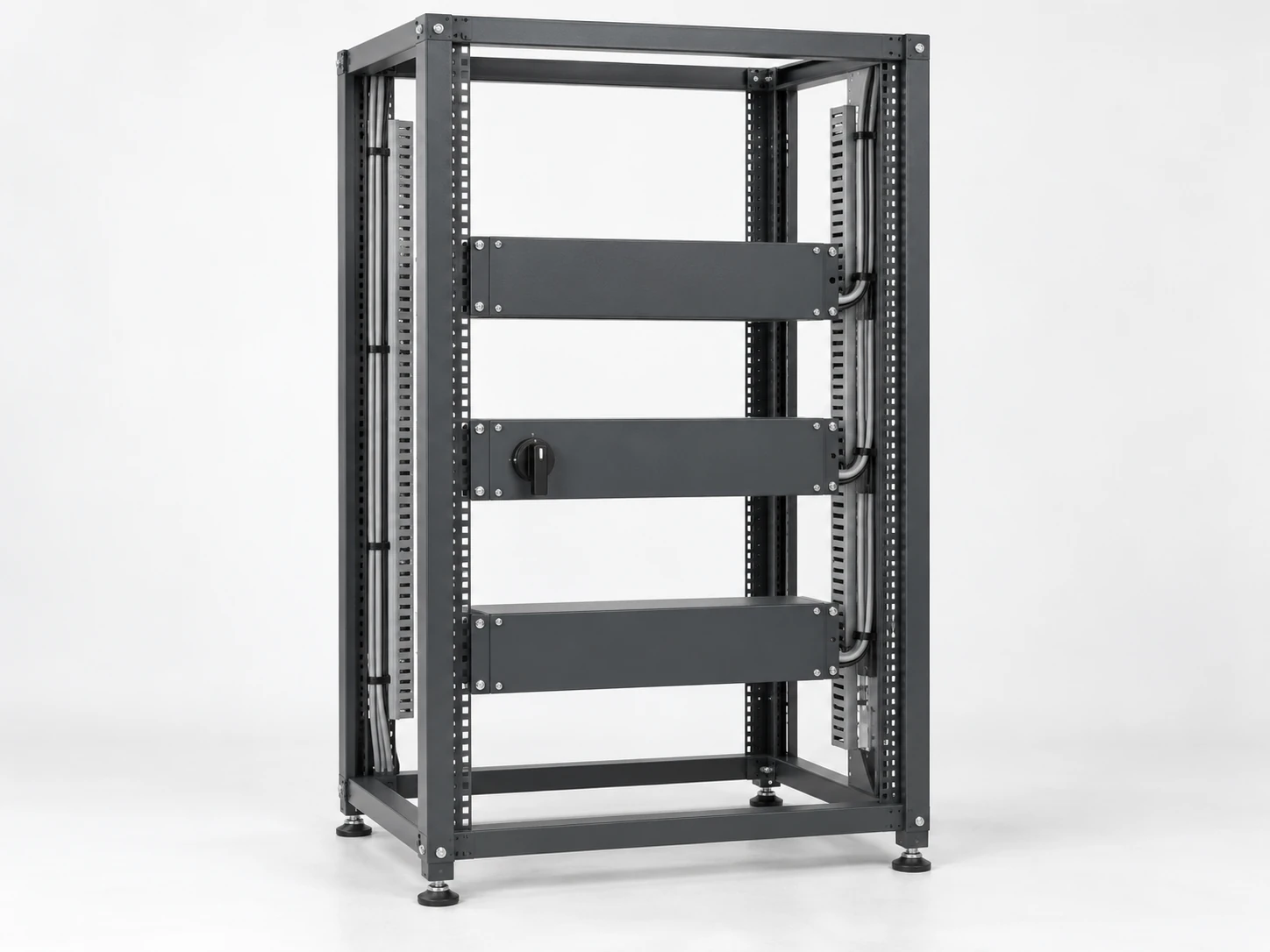
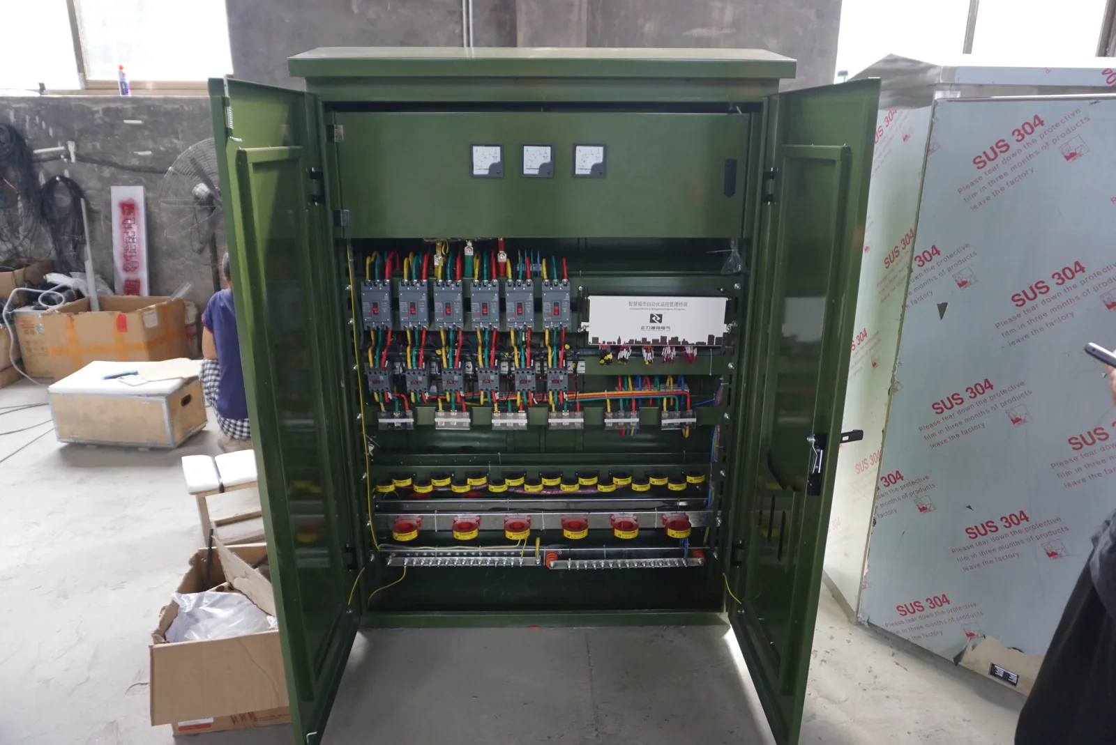
Distribution cabinet assembly showing the physical organization of electrical equipment.
Our distribution cabinets organize incoming power and outgoing circuits for industrial equipment and facilities. We configure the arrangement around your supply, load groups and installation space, connecting circuit planning with the busbars, terminals and access needed for everyday operation.
We approach reactive power compensation around the way your facility operates. By connecting measured demand with source conditions, switching duty and cabinet layout, we help define a configuration that supports better use of the electrical supply.
We coordinate cabinet and distribution interfaces around your rack equipment, selected PDU and incoming circuits. A clear connection map brings outlet allocation, available capacity, mounting space and monitoring requirements into one practical project discussion.
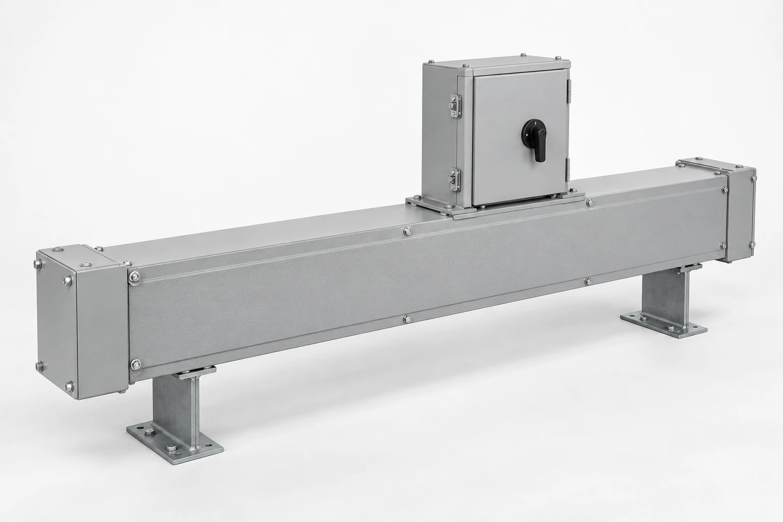
A power cabinet connects to a wider system of conductors, cable entries and support routes. Busbar boxes and busway carry current through defined conductor assemblies; cable trays support the cables themselves. Understanding that difference helps connect the electrical layout to the physical route.
We use the cabinet's terminal positions and cable direction to discuss the surrounding interfaces with you. Bend space, support, connection access and environmental exposure can affect both the route and the enclosure. The topics below explain busbar, busway, branch connections and cable-routing options in more detail.
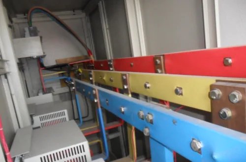
We organize busbar connection-box configurations around your incoming supply, outgoing circuits and installation space. Bringing conductors, supports, terminals and the enclosure together creates a clear interface for power connections and future maintenance.
We connect busway project discussions with the transformers, connection boxes and distribution cabinets at each end of the route. Source connections, branch loads and available space work together to shape a coordinated power-distribution arrangement.
We shape cable-branch enclosure configurations around the circuits they connect. Voltage class, cable construction, entry direction and site conditions guide the arrangement of terminals, supports, seals and accessible connection space.
We work with project teams to connect cable-routing requirements to our cabinet and enclosure interfaces. Cable size, route geometry, supporting structure and installation conditions guide the discussion, helping bring tray, ladder, wire-mesh or trunking routes into a practical cabinet-entry arrangement.
Our electric meter boxes and metering configurations
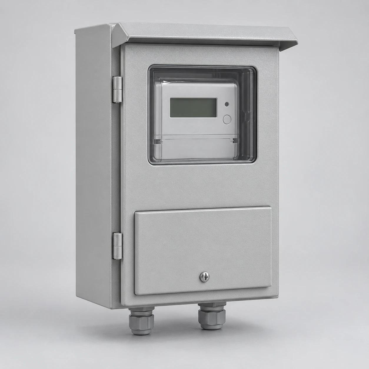
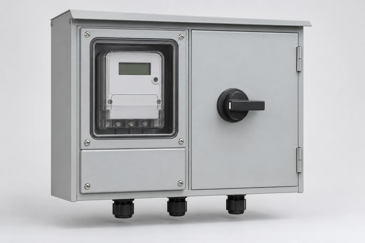
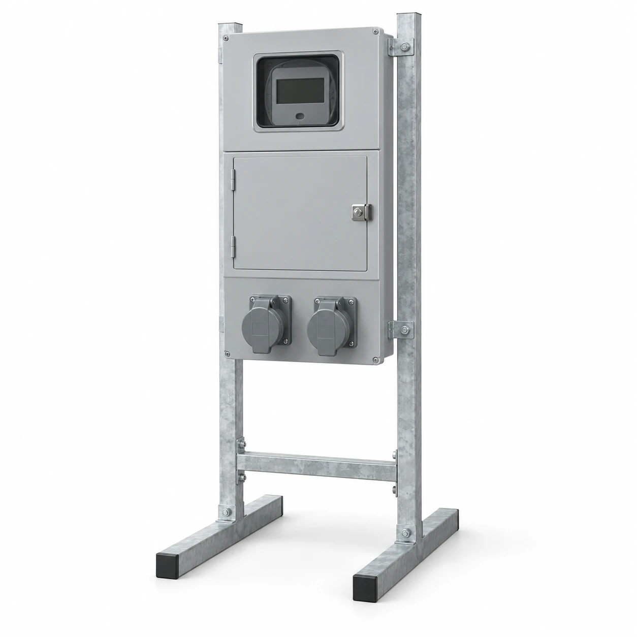
Our meter boxes organize the meter position, incoming and outgoing connections, door access and mounting arrangement. We work around the service format and utility interface, with single-phase, three-phase, direct-metering and CT-metering layouts serving different applications.
Mounting and access that suit the location
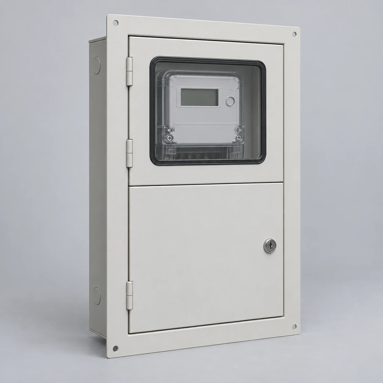
Surface-mounted and recessed constructions meet different building interfaces; outdoor arrangements bring weather exposure into the material and entry design. Multiple accounts require a clear relationship between meter positions and their associated circuits. We discuss these details with the meter format and project layout, so the enclosure supports both installation and ongoing access.
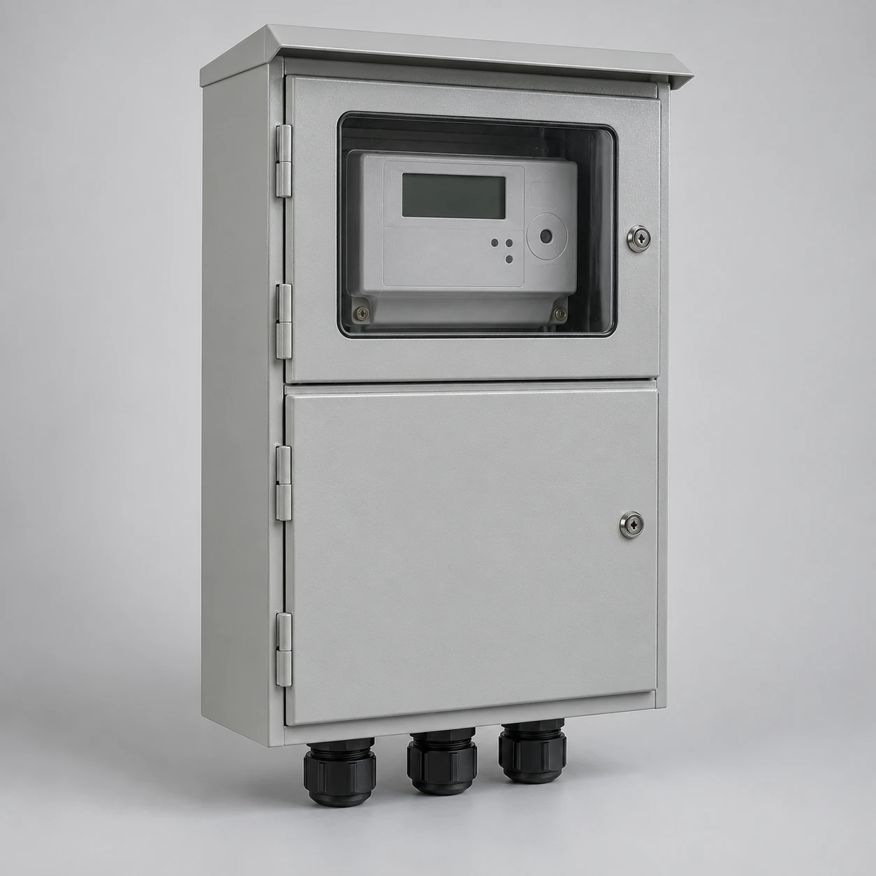
Illustrative configuration: meter viewing and terminal access in separate compartments.
We build meter-box configurations around your meter, service and mounting requirements. Our approach brings the enclosure, equipment layout and cable interfaces together for a clear installation and an accessible metering arrangement.
We configure three-phase meter boxes for commercial buildings, workshops and other project applications. Our layout brings the service conductors, selected meter and cable routes together with the space needed for reading, connection and maintenance.
We configure single-phase meter boxes around the selected meter, its mounting interface and the installation space. For new projects and replacement enquiries, we bring the enclosure, reading access and cable routes into one coordinated layout.
We coordinate meter-main configurations that bring the metering section, main device and outgoing connections into a clear layout. Our project approach links these electrical functions with the enclosure, cable routes and access needed at the installation.
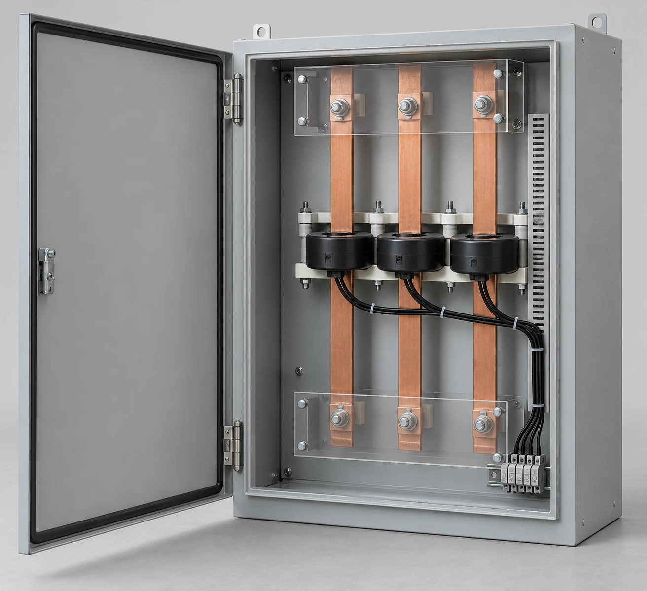
We configure CT metering cabinet layouts around the primary conductors, selected current transformers and meter arrangement. By coordinating mounting space, measurement connections and access, we help the enclosure fit the complete metering application.
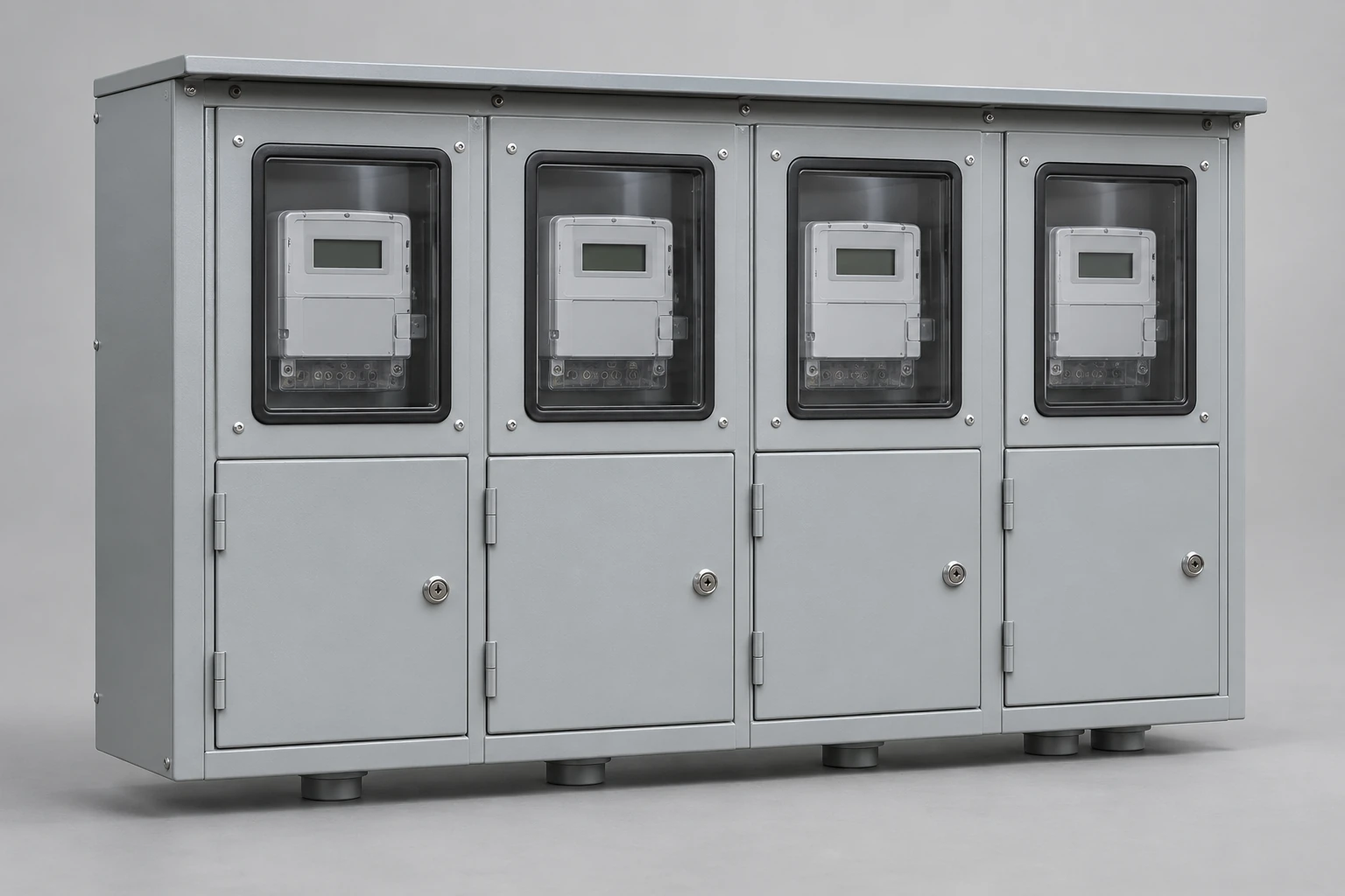
We configure multi-meter enclosures around the users and shared services they support. Clear meter positions, coordinated incoming and outgoing connections, and practical access make the assembly easier to identify, install and manage as the project develops.
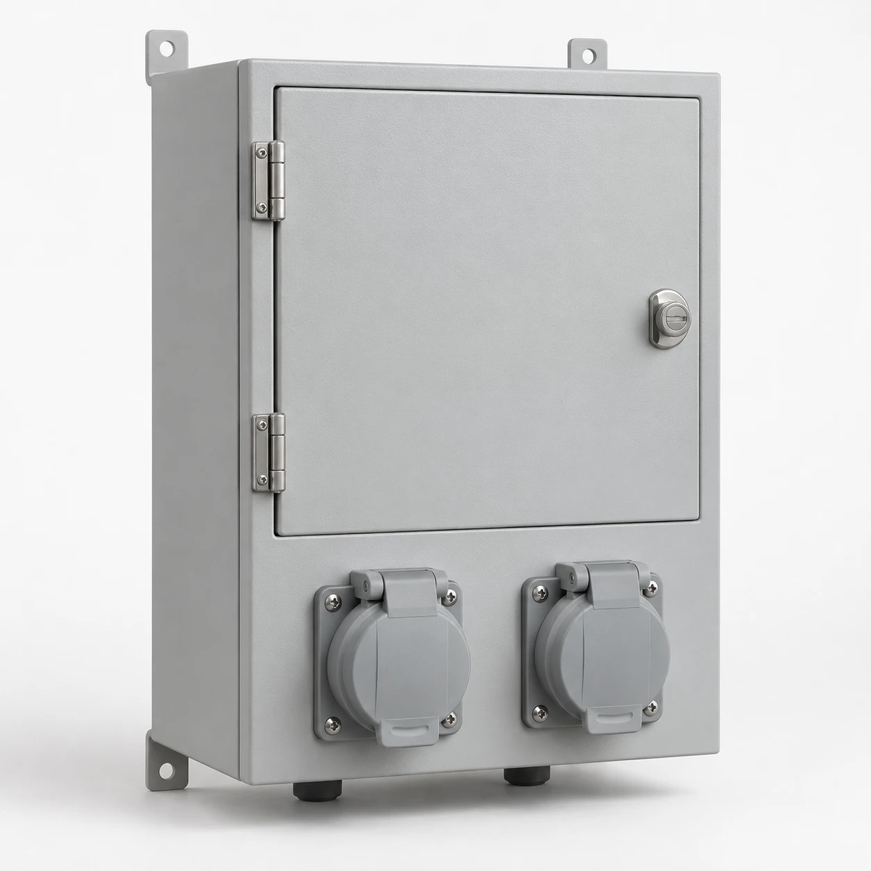
We configure outdoor meter boxes around the conditions at their installation point. Meter interfaces, enclosure materials, door seals and cable entries work together with the mounting layout to support accessible, organized metering outdoors.
We coordinate recessed meter boxes with the wall, meter arrangement and cable space. Bringing the enclosure body into the wall can reduce exposed projection, while a carefully positioned frame and door give the installation a clear, integrated appearance.
We configure surface-mounted meter boxes around the space available on a wall or support. Our layout brings the meter interface, enclosure projection, fixing points and cable approach together for practical reading and service access.
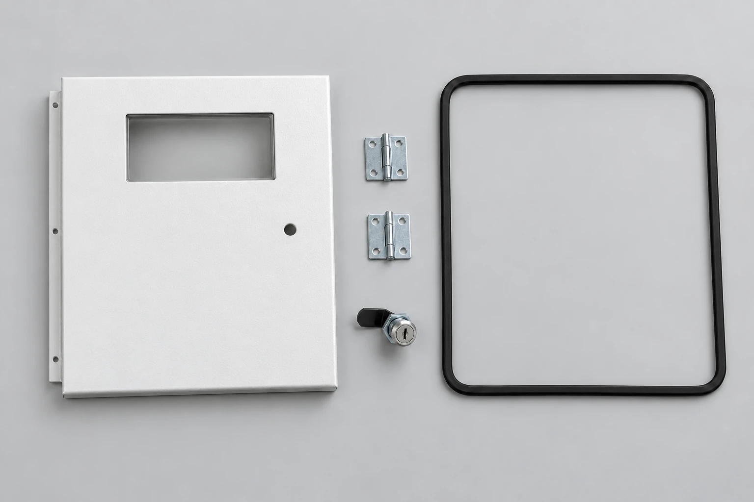
We help you match door, frame, hinge, latch and seal requirements to the existing meter enclosure. Our discussion starts with the box reference and the details that connect the replacement part to the surrounding assembly.
We configure meter enclosures around your selected prepaid or smart meter. Our layout brings together the meter, mounting board, display or customer interface and communication accessories so the hardware fits the installation and its intended use.
We discuss temporary metered-power configurations around the loads, working stages and movement of your project. Our approach brings the metering area, main protection and outgoing connections together with the enclosure and its support interface.
Our control cabinets bring the machine's signals, switching devices and power connections into an organized assembly. We work from the operating sequence and field interfaces toward device positioning, terminal groups and an accessible wiring layout.
Motor-control projects add the behavior of the driven load: starting current, acceleration, repeated starts and any speed-control requirement. Those conditions help frame the choice between starting and drive arrangements. Our control and motor-control pages explain how the electrical function, operator interface and cabinet heat load connect.
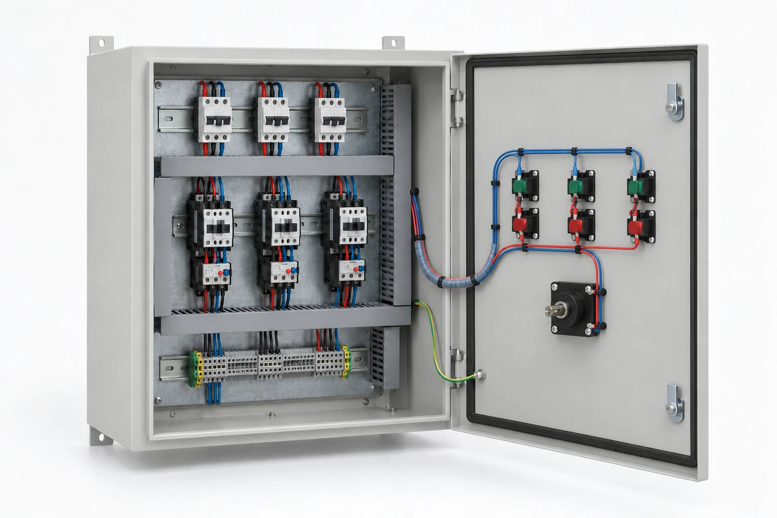
Control hardware and wiring arranged inside an electrical cabinet.
Our industrial control cabinets connect machine functions with an organized hardware layout. We work through power, control devices, I/O and field terminals together, giving your equipment team a clear connection between the operating requirement and the cabinet's physical arrangement.
We configure motor control cabinets around the motor and the equipment it drives. Pumps, fans, conveyors and other loads bring different starting and running demands, so we connect the control method with the power circuit, command interfaces and cabinet layout from the beginning.
Our enclosures, cooling arrangements and cabinet accessories
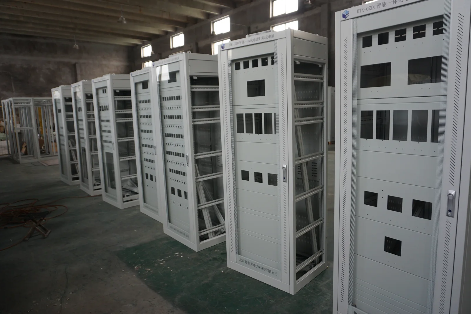
We develop the cabinet structure around its contents and installation. Mounting plates, door openings, cable entries and removable parts shape access for assembly and maintenance. Material and surface treatment are discussed in relation to moisture, corrosion exposure, mechanical demands and appearance.
Cooling forms part of the same design. Ventilation exchanges air, while heat exchangers and enclosed cooling approaches separate the inside from the surrounding environment in different ways. Hinges, locks, seals and mounting hardware then need to fit the chosen construction. Our enclosure topics bring these choices together.
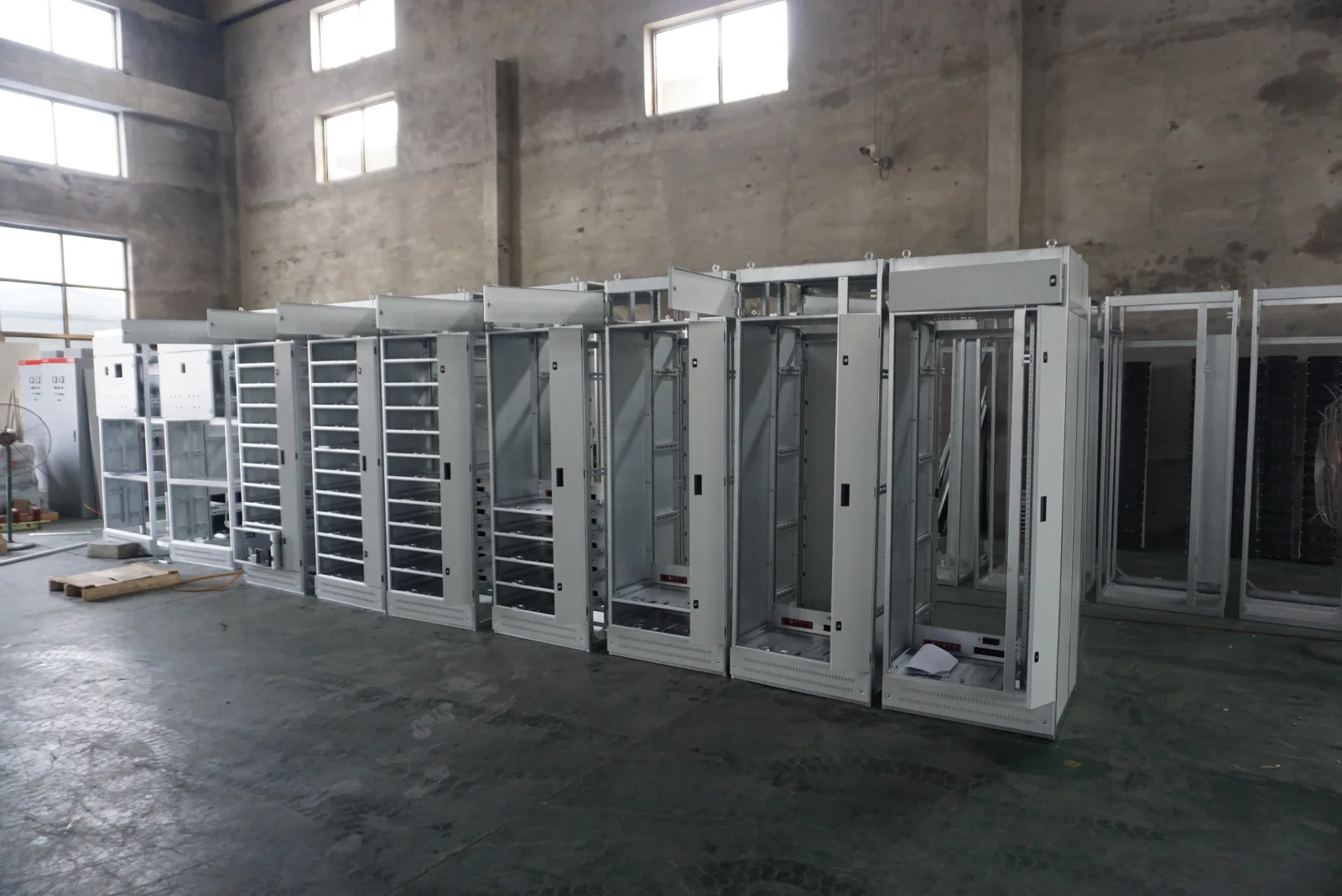
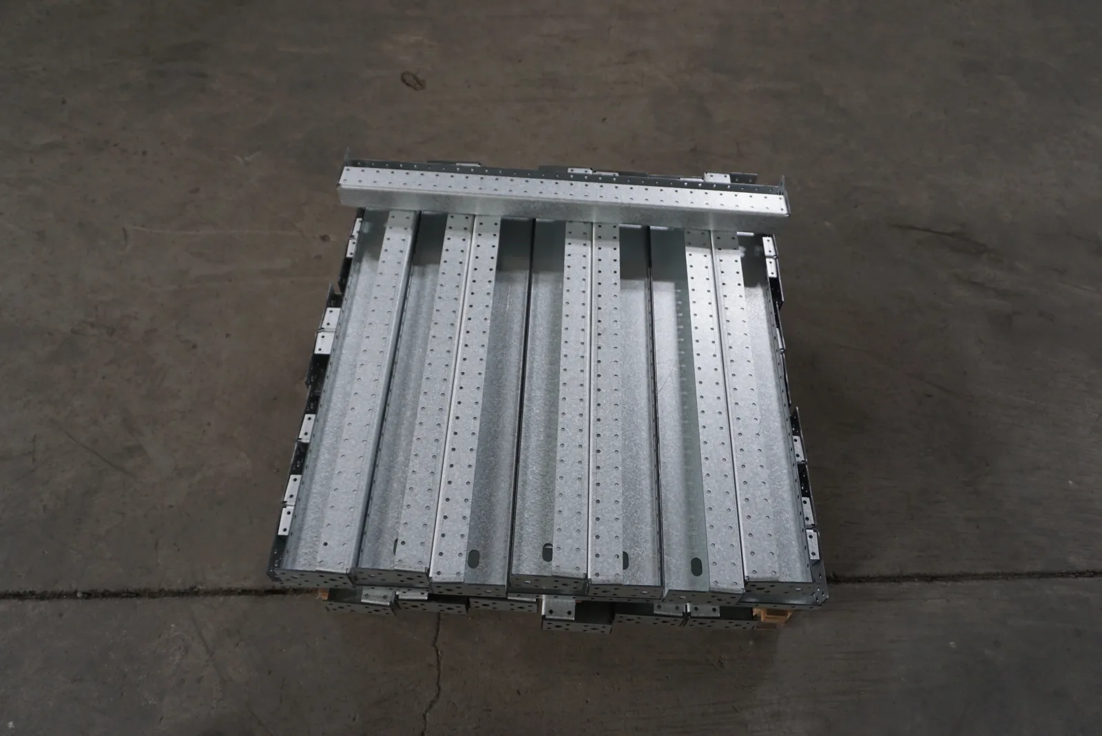
Cabinet frames and formed mounting structures during fabrication.
We manufacture electrical enclosures around your equipment layout. From the cabinet frame to the mounting plate and door openings, we coordinate the mechanical details that make equipment installation and daily access practical.
We bring heat management into the cabinet layout from the start. Equipment losses, ambient conditions and available cooling services guide the method, while airflow, openings and maintenance access shape the installation.
We coordinate cabinet accessories around the parts they connect. Door hardware, equipment supports and cable-entry fittings work best when their dimensions, materials and mating surfaces are considered together.
Cabinet and DC interfaces around batteries and charging
Battery and charging applications connect mechanical support with DC power, protection, monitoring and thermal management. A battery enclosure must work with the battery arrangement, connection access and system interfaces; the surrounding equipment can also need auxiliary AC power and DC distribution.
We discuss the relevant cabinet and power interfaces with your battery, charger or system team. Continuous loads and battery-recharge demand can occur together, while communication and alarm functions have their own connection needs. Our related pages explain these relationships without treating the enclosure as the whole energy-storage system.
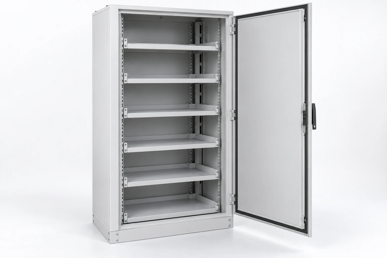
Illustrative configuration: an empty module cabinet with support shelves and cable-routing space.
We develop cabinet and rack arrangements around your specified battery modules. Module supports, cable routes, cooling interfaces and service space come together in a layout that fits the equipment and installation.
We help turn industrial DC load and battery-charging requirements into coordinated cabinet layouts, power connections and equipment interfaces. Our work connects the selected rectifier, battery and control equipment with the space, terminals and operating conditions of your project.
Enclosures and controls at building and lighting interfaces
Lighting controls, junction boxes and building power connections bring the equipment interface close to the point of use. Their layout depends on the connected load, cable system, mounting position and the environment around the connection.
We use these topics to discuss how cabinets and connection spaces support the wider installation. A lighting driver has an electrical relationship with its luminaire and control signal; a junction enclosure needs room for terminations and cable support. The following pages explain those specific choices and their relationship to the equipment layout.
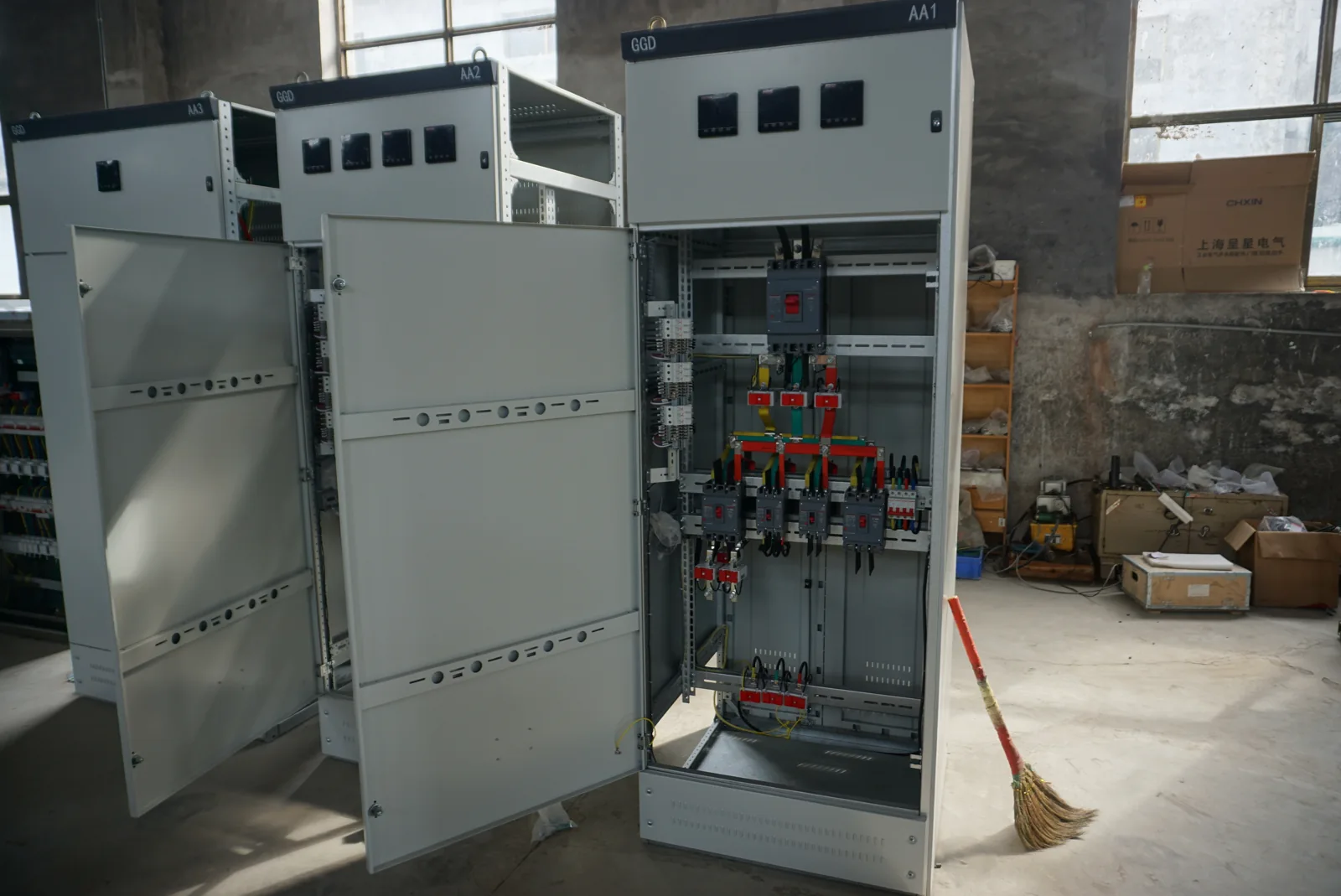
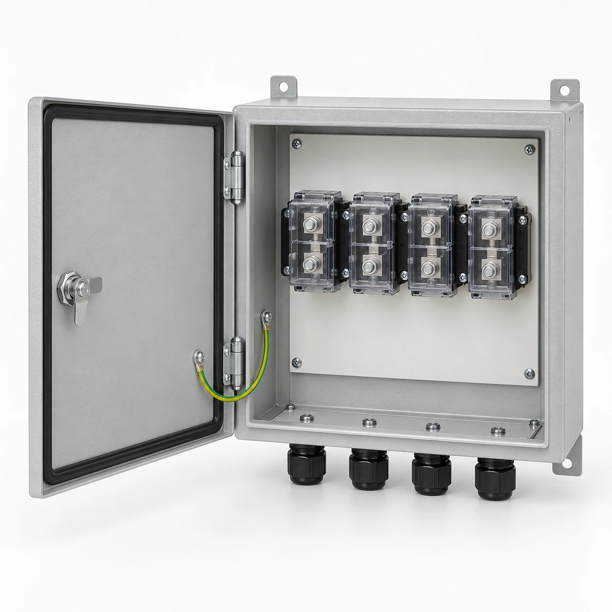
Cabinet construction showing component mounting and wiring access.
We help connect lighting equipment requirements with practical cabinet and power interfaces. Your selected fixtures, drivers and controls guide our discussion of mounting, terminals, cable routes, heat removal and the documents needed for the project.
We configure local connection enclosures around the cables and terminals your project needs. Lighting, control and power connections guide the box layout, usable space, cable entries and access, bringing the electrical connection and its physical installation together.
We help align specified outlets and switches with the boxes, mounting details and power connections around them. Our project discussion brings together the connected load, exact device interface and installation space so the electrical and mechanical details work together.
Auxiliary power and control interfaces around generators
A generator's fuel arrangement connects with pumps, level monitoring, alarms and operating controls. Our discussion focuses on the cabinet, auxiliary-power and electrical-control interfaces around those functions, alongside the generator and fuel-system specialists.
Pump duty, supply voltage, signal types and the response to operating conditions help define the electrical interface. Clear connections between the generator controls, site equipment and cabinet make the project discussion more useful than starting with an enclosure size alone. Our application page organizes these relationships for the project team.
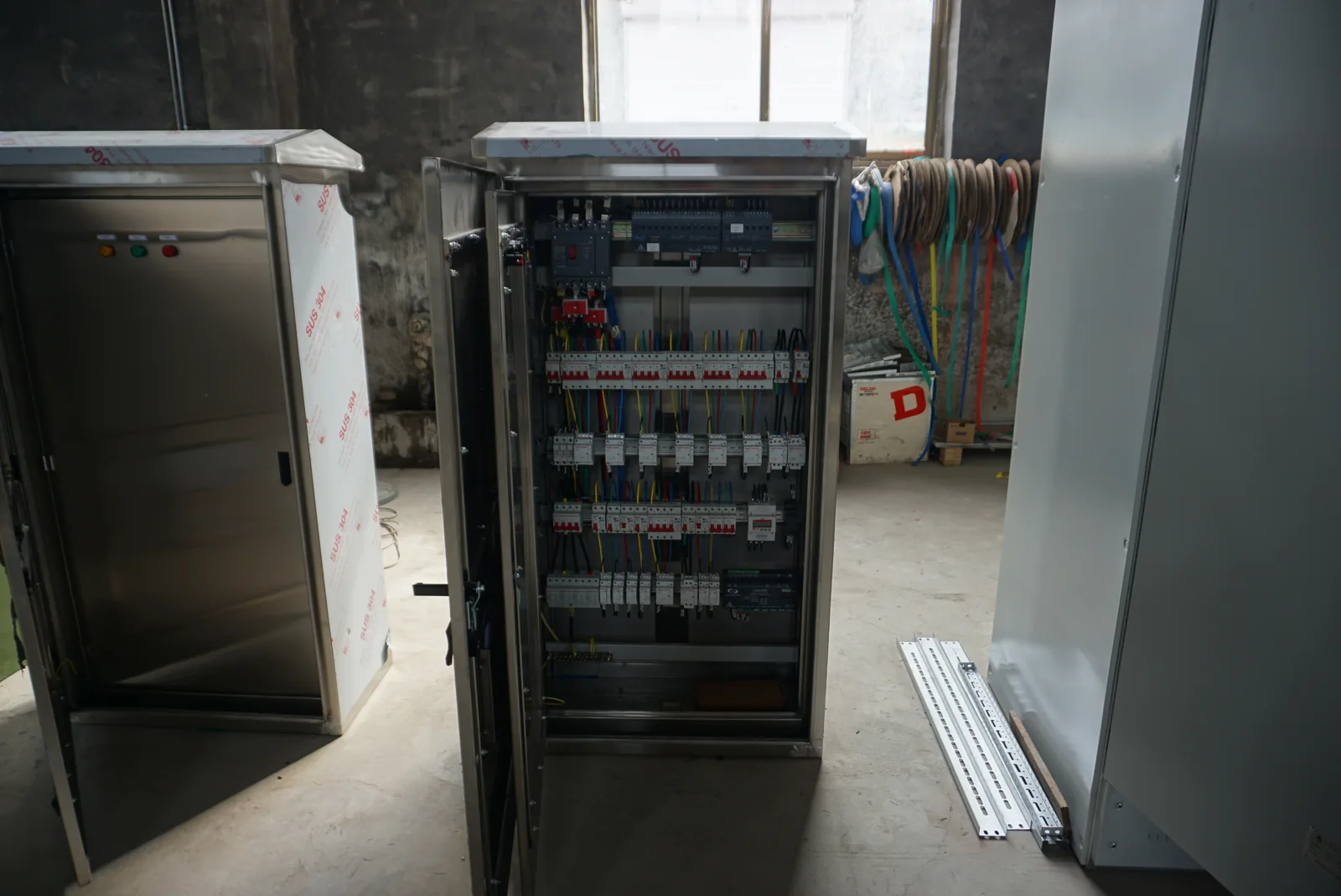
Cabinet interior showing component mounting, wiring routes and service access.
We coordinate auxiliary power and cabinet interfaces for generator projects. The selected generator and fuel arrangement help define pump, heater, monitoring and control requirements; we bring those electrical loads and signals into the power-distribution and enclosure discussion.
If your project combines transformers, power supplies, cabinets and metering, we can work through the connections with you. An equipment list or one-line diagram helps show what needs to be supplied, controlled or measured and where the items meet.
Share the application, destination and the electrical information available. We can discuss the relevant product ranges, enclosure layouts and project interfaces together. If your search does not return a matching topic, describe the function you need in the inquiry; it is a useful starting point for the conversation.