METERING CABINETS · PRIMARY AND SECONDARY INTERFACES
CT Metering Cabinets
We configure CT metering cabinet layouts around the primary conductors, selected current transformers and meter arrangement. By coordinating mounting space, measurement connections and access, we help the enclosure fit the complete metering application.
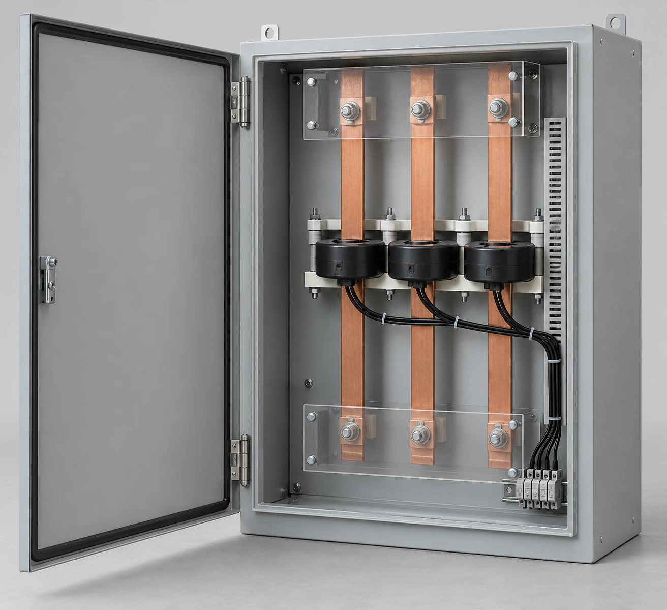
Illustrative configuration: CT positions, guarded conductor paths and secondary-wiring space.
Our cabinet configuration follows the project's service arrangement and metering requirements. CTs, meters, test facilities and enclosure components are identified separately in the agreed supply scope, with the serving utility's requirements incorporated where applicable.
Arrange the power path and measurement path together
A metering CT produces a measurement signal related to the current in the primary circuit. The main load remains on that primary path, while the meter receives the secondary measurement input. This differs from a power transformer used to change the voltage supplied to equipment.
Two paths shape the cabinet
Primary power: incoming source → conductors through or connected to the selected CT arrangement → downstream load.
Measurement: CT secondary → designated terminals and test facilities → meter input, with voltage sensing arranged separately where required.
We use these functional paths to organize conductor space and measurement connections. The project circuit diagram defines the actual wiring and protective-device positions.
Coordinate each metering component with its enclosure space
We connect the service arrangement with the CT mounting, meter position and compartment layout. Utility metering and private measurement may use different equipment and access rules, so their requirements enter the configuration discussion at the start.
How the metering arrangement shapes the cabinet
Configuration element
Layout relationship
Primary conductors
Incoming route, CT interface, supports and outgoing path
CT mounting
Window or terminal geometry and fixed mounting positions
Secondary and test interfaces
Identified terminals, lead routing and authorized access
Meter position
Mounting format, input connections and reading space
Cabinet divisions
Barriers, doors, seals and service areas
Keep CT ratio, meter input and cabinet duty distinct
The CT ratio relates primary current to its specified secondary output. The meter must accept that output and use the intended measurement configuration. Frequency, operating-current range, accuracy designation and burden conditions also influence the selected combination.
Use each parameter for its own purpose
The cabinet's current duty, the CT ratio and the meter input rating describe different interfaces. We keep them separately identified when coordinating the arrangement. This helps avoid selecting the enclosure from a CT ratio alone or treating two meters with similar housings as electrically interchangeable. Exact component references connect these parameters with the physical layout.
Consider the leads as part of the measurement chain
For a current-output CT, the meter and secondary circuit place an electrical burden on the CT. Lead resistance contributes to that burden, so lead length and routing can affect whether the complete chain remains within its intended measurement conditions.
Coordinate a separate meter position
Placing the meter in another compartment or enclosure changes more than the mounting location. We discuss the route between CTs, test facilities and meter inputs alongside the metering designer's burden assessment. Keeping the component and lead schedule together helps maintain a consistent measurement arrangement when the cabinet dimensions or meter location change.
Fit the CT mounting to the primary conductors
CT windows, mounting feet and connection points need to suit the actual cable or busbar arrangement. Multiple conductors, cable bends and support locations can occupy much more space than the CT body alone. We coordinate those envelopes before settling the cabinet depth and connection positions.
Make physical and circuit identification agree
For a window-type CT, the conductor route must fit the specified opening and installation arrangement. Other constructions have their own mounting and termination requirements. CT references, polarity markings and circuit labels stay connected to the primary and meter-channel identifiers, helping the installed layout remain understandable during commissioning and later work.
Organize secondary terminals and testing access
Test facilities and any required shorting provisions follow the selected CT and metering scheme. We discuss their mounting space, identification and position within the enclosure so authorized personnel can reach the intended interface without confusing it with adjacent circuits.
One enclosure or separate compartments
CTs, meters and test equipment may occupy a shared assembly or separate spaces according to the project arrangement. Barriers, lead entries and door access follow that choice. CT secondary circuit work and testing require qualified personnel using the applicable equipment and utility procedures; the cabinet layout supports those procedures without substituting for them.
Combine structural support, insulation and controlled access
We relate cabinet materials and mounting construction to conductor loads, CT support and the installation environment. A rigid mounting base helps keep component positions stable, while insulating supports and barriers establish the separation required by the selected arrangement.
Plan reading and service areas
Doors, seal positions and viewing areas distinguish routine meter reading from restricted access. Their locations also influence cable routes and the available mounting surface. For outdoor applications, finish, gasket and entry choices address moisture and corrosion conditions. Our outdoor meter boxes page explains these environmental considerations in more detail.
Our coordinated metering layout follows one set of identifiers
We connect the general arrangement, primary conductor route, CT schedule and secondary terminal layout with the meter position and sealing boundaries. Consistent identifiers make it easier to follow a circuit from its physical location to the relevant drawing.
Keep changes connected
A different CT can change its window, mounting points and output conditions. Moving a meter can change lead routing and burden. We bring these related effects into the configuration discussion rather than treating each change as an isolated enclosure edit. The agreed layout and component schedule provide a shared reference as the project moves toward fabrication.
Coordinate project documents and delivery details
The project document package links the cabinet layout to the selected components, terminals and agreed inspection requirements. Ratio, polarity and meter-configuration checks can be defined with the responsible metering team as part of the project's acceptance arrangements.
Protect instruments and preserve configuration records
Delivery planning includes the identification and protection of instruments, mounting parts and loose accessories within the selected supply scope. A component inventory connects those items to the drawing positions. Keeping the final layout, component references and operating information together supports fault reporting, maintenance planning and future discussions about a changed meter or CT.
Discuss your CT metering cabinet with us
Start with the metering purpose, the primary conductor arrangement and the meter or CT information already available. Tell us where the cabinet will be installed and how many units the project needs. We can organize the cabinet discussion around those essentials while the remaining component details are developed.
Existing utility drawings, equipment references and layout sketches can be exchanged during the project. If the metering format is still being selected, explore our electric meter boxes. For equipment that changes the load's supply voltage, our transformer applications page covers the separate power-conversion interface.