
Temporary Power Meter Panels
We discuss temporary metered-power configurations around the loads, working stages and movement of your project. Our approach brings the metering area, main protection and outgoing connections together with the enclosure and its support interface.
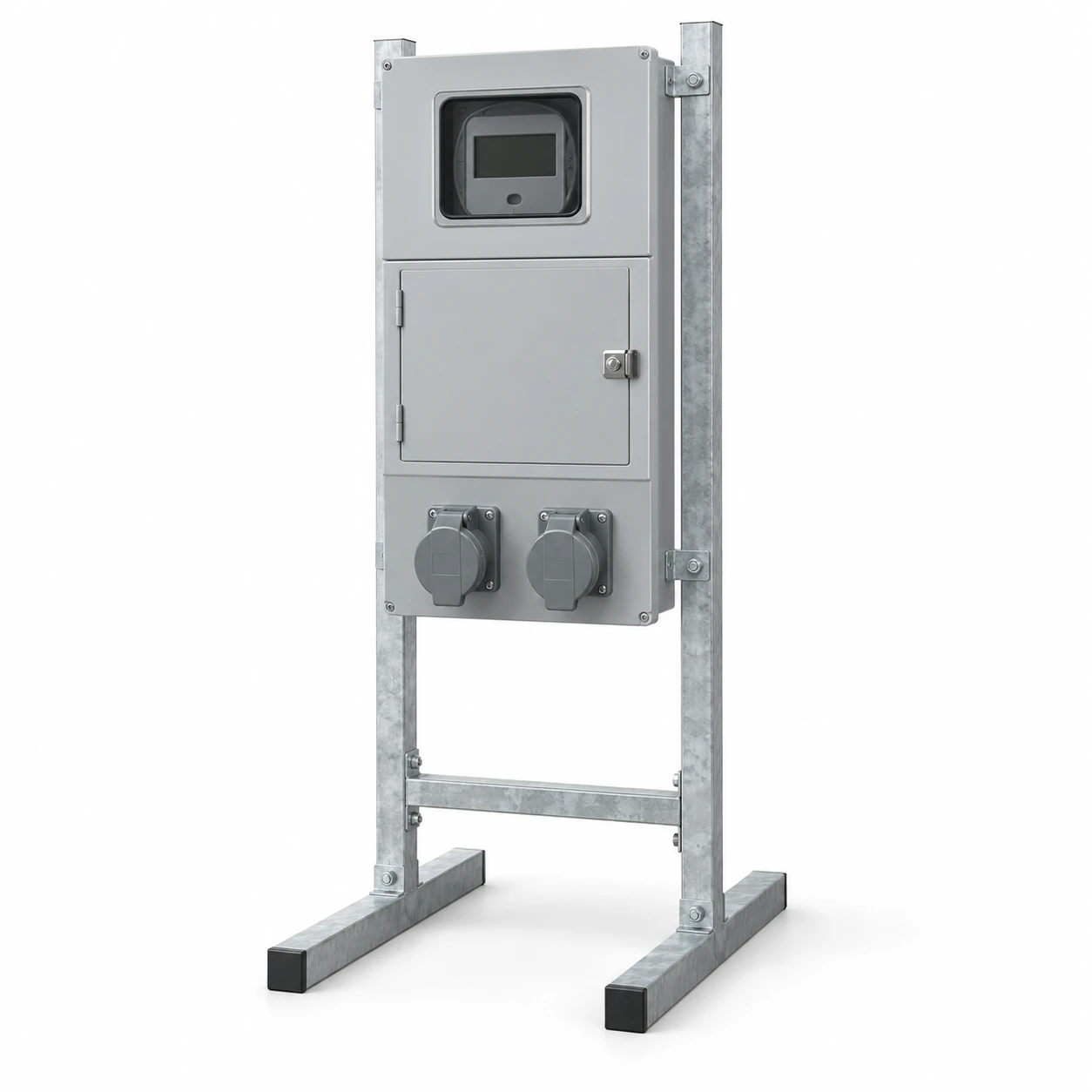
We define the panel and selected devices alongside the project support, cable and service connections. This keeps the equipment configuration aligned with the site team responsible for installation and supply coordination.
Our temporary-power discussion follows the project stages
A construction project can change its loads, working area and supply routes as the work progresses. We begin with the temporary purpose, planned duration and expected moves so the equipment discussion reflects how the panel will be used.
The initial location, later positions and surrounding activity can affect cable entry, support and access. We coordinate these conditions with the project's metering and distribution needs, rather than considering the panel in isolation. Identifying which loads remain throughout the project and which belong to a particular stage helps us organize the circuit and connection discussion.
Separate the application from the support style
We coordinate the selected cabinet and connector interfaces around how the supply will be used. Pole-mounted describes a support arrangement; temporary describes a period of use. Neither term alone determines the service category, meter interface or outlet configuration.
| Project context | Application distinction | Our configuration discussion |
|---|---|---|
| Construction temporary power | Loads and working positions can change during defined project stages | Site-load schedule, planned moves, outlet designations, panel mounting and cable access |
| RV or caravan connection | The vehicle or pitch connection has its own specified electrical interface | Selected connector, voltage and phase, connected load, metering role and enclosure access |
| Mobile-home or pole-mounted service | A pole or other support can serve an ongoing installation as well as temporary work | Project service classification, utility arrangement, main equipment and cabinet-to-support interface |
We define the included enclosure and fitted components in the quotation, coordinated with the project team's service and support arrangements. For ongoing service installations, our meter-box configurations and meter-main arrangements explain the housing, metering and main-equipment interfaces.
We organize the panel around loads and connection interfaces
We use the load schedule to connect the equipment on site with its outlets or fixed connections. Simultaneous use and starting demand influence the configuration alongside each load's nameplate information.
| Input | Configuration role |
|---|---|
| Equipment and quantity | Number and purpose of the outgoing connections |
| Voltage, phase and frequency | Supply and device interfaces |
| Demand and starting behavior | Operating conditions considered with the site design |
| Connector designation | Outlet type, location and mating equipment |
| Circuit arrangement | Feeder, branch and protective-device layout |
| Work location | Cable route, exposure and access |
We keep spare connection positions distinct from electrical capacity reserved for later equipment.
Our metering layout follows the site service arrangement
We coordinate service voltage, frequency, phase and conductors with the utility's selected meter or socket interface. The incoming route, service equipment and metering position establish the connection between the site supply and the panel.
The meter-box range explains the roles of the housing, socket, meter and protective equipment. We use that same distinction to identify the components in the temporary project. The utility and site team coordinate the service connection and meter provision, while our equipment discussion follows the agreed layout and supply scope.
We connect the meter, main and outgoing sections
Supply and metering area
The selected service interface shapes the incoming terminals, meter location and required access. We coordinate that area with the main device and the site cable approach.
Outgoing connections
The branch schedule determines the device and connector locations, with operating access and cable routing considered together.
Functional relationship: site supply → metering → main/protective section → outgoing circuits and outlets. The project support carries the assembled panel.
Our meter-main combinations content develops the relationship between metering, main equipment and outgoing circuits.
We coordinate circuit protection with the site design
We bring the main and branch devices into the circuit layout using the project's electrical requirements. Available fault current, operating voltage and the selected assembly/device combination are considered alongside normal load demand.
Ground-fault protection and grounding arrangements follow the actual site plan and its applicable requirements. We coordinate the specified protective devices, connections and identification within our equipment scope. The project team defines the installation and required site checks, while the agreed device and circuit schedule provides a common reference for the panel configuration and later changes.
Our equipment interfaces connect with the site work
We identify where the panel meets its support, site cables and service equipment. This helps the project team coordinate the physical assembly with the surrounding work.
| Area | Our equipment information | Site interface |
|---|---|---|
| Panel and devices | Layout and selected-component schedule | Required loads and operating locations |
| Mounting | Fixing dimensions and assembled weight | Selected stand, pole, base or other support |
| Connections | Terminals, entries and outlet positions | Cables and grounding arrangement |
| Metering | Specified meter interface and access | Utility service coordination |
| Project stages | Equipment and circuit identification | Installation, relocation and removal plan |
We consider exposure in both use and movement
Rain, dust, sunlight, corrosion and accidental impact influence the enclosure and mounting discussion. We consider panel rigidity, surface protection, hardware and door seals together with the expected working environment.
Outlet covers and entry fittings also need to suit the intended operating condition, including the arrangement with the specified plugs connected. The outdoor meter boxes content develops these enclosure interfaces. We distinguish assembled weight from shipping weight and coordinate the mounting drawing with the site support. Travel routes and handling between positions add another practical consideration to the chosen layout.
Our project documents support delivery and identification
We connect the general arrangement, circuit and outlet schedule, terminal information and mounting interface to the selected configuration. Circuit and component references help the receiving and installation teams relate the equipment to the project drawings.
We discuss packing around the enclosure, outlet covers, fitted devices and any included support hardware. Packed dimensions and gross weight help with transport and unloading preparation. The agreed delivery information identifies the supplied components and relevant instructions, while dimensional and functional checks are coordinated with the equipment scope and project requirements.
We keep configuration information useful between site stages
Movement and team handover
A new location can change cable routes, support conditions and exposure even when the connected loads remain the same. We use the equipment reference and updated layout information to discuss any required configuration changes with your team.
Circuit identification, component references and outstanding condition observations help the next site team understand the arrangement. Qualified personnel assess the installation and required checks after relocation and coordinate removal when the temporary use ends.
During normal use, visible damage or repeated tripping should be reported through the site's professional service route. Protective devices must remain in operation; they are not bypassed to keep work running.
Tell us about your temporary metered-power project
Start with the intended use, project duration and principal loads. Add the outlet or connection requirements, expected moves, service arrangement and quantity if known. We can then discuss the panel layout and support interface with your team.
Site and utility drawings help develop the later connection details. Let us know which project stages use the equipment and how it will move between them, so the enclosure, cable access and delivery discussion reflect its practical use.