
Power Distribution Cabinets
Our distribution cabinets organize incoming power and outgoing circuits for industrial equipment and facilities. We configure the arrangement around your supply, load groups and installation space, connecting circuit planning with the busbars, terminals and access needed for everyday operation.
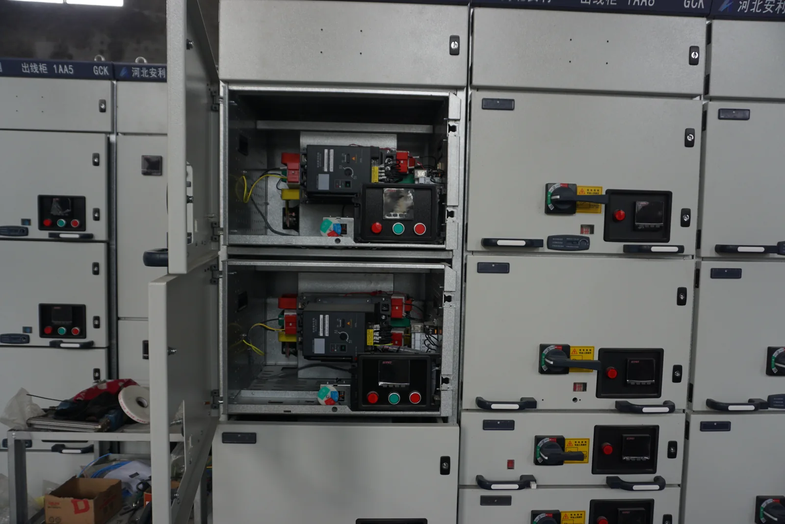
Power organized around the way your facility operates
A distribution cabinet receives power at an incoming connection and divides it among identified circuits. Grouping those circuits around a production line, machine area or equipment room makes the power arrangement easier to understand and connects each feeder with the load it serves.
We start with that operating purpose, then discuss the incoming device, bus system, outgoing devices and circuit identification as one cabinet configuration. Functional path: source → incoming equipment and busbars → outgoing protection → load groups. When the application also needs voltage or frequency conversion, our power supply cabinets address that additional function.
Bring the incoming supply into the configuration
Incoming voltage, frequency, phases and grounding arrangement determine the starting interface. Line-to-line and line-to-neutral references are kept explicit so the same voltage description carries through the circuit plan and equipment connections. We coordinate the main-device and terminal arrangement with the site's incoming cable approach.
Source capacity and available fault current influence different parts of the design. The first relates to the demand the supply can serve; the second affects protection and assembly duty. If the installation includes multiple sources, their permitted connections and transfer functions are considered alongside the incoming section. This gives the project team a consistent basis for cabinet and site decisions.
We identify the voltage class and assembly type before developing the outgoing-circuit layout. Where the project concerns medium-voltage circuits or fixed and withdrawable switching structures, our switchgear configuration page explains the related insulation, switching and access requirements.
Translate outgoing loads into a practical circuit layout
| Circuit information | Configuration effect | Operating value |
|---|---|---|
| Load purpose and identifier | Feeder grouping and circuit labels | Clear connection between device and equipment |
| Voltage and phase arrangement | Pole arrangement, neutral and terminal allocation | Consistent power interfaces |
| Running and starting demand | Device duty and aggregate load assessment | Configuration follows actual operation |
| Cable and monitoring needs | Terminal space, entry direction and signal provision | More organized installation and indication |
For a production line, motors and heaters may follow different sequences. In an equipment room, continuously supplied electronics may dominate the duty. We use those distinctions to discuss circuit grouping and interfaces; dedicated starting or speed-control functions connect to the motor-control configuration.
Plan spare devices, reserved positions and future capacity
Installed spare devices
A fitted spare device reserves a defined piece of equipment within the assembly. Its circuit purpose and connection arrangements can be kept in the schedule even before the future load is installed.
Reserved physical positions
An allocated position leaves room for later hardware. We distinguish empty space from prepared connections and fitted equipment, so the expansion discussion describes the physical condition clearly.
Electrical capacity for future loads
Additional circuits also need capacity in the supply, incoming equipment, busbars, terminals and thermal arrangement. We discuss future demand with the initial circuit plan. Keeping space and electrical capacity separate helps customers plan growth without treating an unused compartment as an automatic increase in available power.
Protection coordinated from incoming supply to feeder
Incoming equipment, busbars, outgoing protective devices and circuit connections form a complete power path. Their behavior during a fault depends on the system conditions and the selected device combinations. A breaker's individual marking describes that device; the assembly has its own duty and construction requirements.
We coordinate the cabinet information with the project's source and protection design. The relationship between incoming and outgoing devices matters to how faults are cleared and how the installation is organized. Keeping source assumptions and circuit changes connected to the configuration also helps the electrical team assess later additions or equipment substitutions.
Busbars and terminals connect the electrical and physical design
Busbar conductor material, cross-section, support arrangement and insulation are linked decisions. Copper and aluminum lead to different conductor and connection details, and the chosen terminal system must suit the cable material and arrangement. We discuss these choices with the required current and installation geometry together.
Neutral duty follows the actual load mix, while protective-conductor arrangements follow the system design. Incoming and outgoing terminal groups are organized by circuit identifiers and cable routes. That keeps connection space, labels and the circuit directory aligned. A clear terminal plan also gives future maintenance work a reference that goes beyond the appearance or position of a device.
Enclosure construction that fits the environment and access
Materials and exposure
Indoor equipment rooms and outdoor locations place different demands on the enclosure. Moisture, dust, contaminants and cleaning conditions shape the material, finish and sealing discussion. We connect those conditions to the cabinet construction and cable-entry arrangement rather than applying a single enclosure description to every installation.
Heat and service space
Device and conductor losses contribute to cabinet temperature. Cooling paths must work with the layout, while door movement and equipment access remain practical in the installed position. We consider cable bends and termination space alongside the footprint. Room for an operator to observe indications and room for qualified maintenance work serve different needs, both worth resolving early.
Our configuration drawings and project information
We bring the one-line, circuit schedule, general arrangement and terminal information into the agreed project documentation. Each describes a different view of the same cabinet: electrical function, individual loads, physical layout and external connections. Consistent identifiers help your team move between those views.
Component details, nameplate information and agreed inspection records connect the design to the delivered equipment. The applicable project requirements are incorporated into that document plan. When a circuit or component changes, the corresponding references are updated together, keeping installation and maintenance information useful throughout the equipment's service life.
Prepare the cabinet for installation and receiving
Inspection items are agreed around the selected assembly, its circuit identification and the relevant functional checks. We coordinate document revisions and component information with the project so the equipment and accompanying records remain aligned.
Delivery planning connects packing dimensions, equipment identifiers and handling information with the site's receiving arrangements. Access restrictions can influence transport sections or unloading plans before dispatch. Qualified personnel carry out site connections, verification and energization using the final design and equipment instructions. During operation, clear labels and instructions help staff identify the circuit involved and report abnormal indications accurately.
Discuss your supply, circuits and expansion plans
Tell us the available supply and the equipment or areas you want to serve. A circuit overview or existing drawing is a useful starting point. We can then discuss feeder grouping, cabinet layout and any planned expansion with your team, developing the detailed requirements as the project takes shape.
The circuit directory and component identifiers also support later conversations about replacement parts or changed loads. Keeping a record of added, removed or reassigned circuits preserves the connection between labels and the actual installation. Include quantity and destination when known, along with any important space or access constraint.