
DC Power and Battery-Charging Cabinet Interfaces
We help turn industrial DC load and battery-charging requirements into coordinated cabinet layouts, power connections and equipment interfaces. Our work connects the selected rectifier, battery and control equipment with the space, terminals and operating conditions of your project.
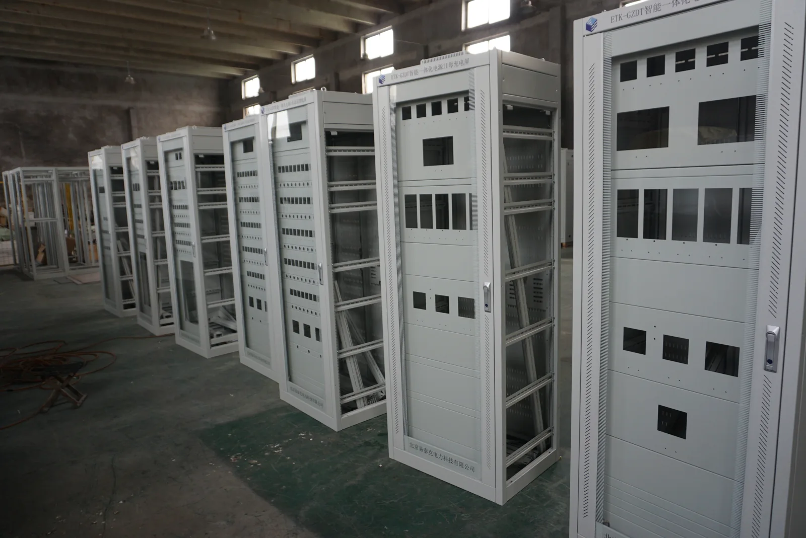
Our cabinet and power-supply project work starts with your DC load profile and selected equipment. Together with your system team, we define the hardware, interfaces and documentation included in the project.
Our Cabinet Interfaces for Industrial DC Power
Control circuits, monitoring equipment and other auxiliary loads need a defined DC supply through normal operation and supply disturbances. We organize the cabinet around that duty, including the selected power equipment, distribution connections and access for service.
| Application | Operating requirement | Cabinet interface |
|---|---|---|
| Industrial DC auxiliary supply | Continuous and intermittent DC loads | Power-equipment mounting, terminals and circuit identification |
| Load supply with battery recovery | Operating loads and recharge demand occur together | Distribution space, charging interfaces and heat removal |
| Selected battery charger | Charging behavior matched to a specified battery | Connectors, control signals and maintenance access |
This application information gives us a practical starting point for arranging the enclosure and its electrical interfaces.
Choose the cabinet discussion by the equipment inside
| Application | Energy path and equipment | How we develop the cabinet interface |
|---|---|---|
| Industrial DC loads and stationary battery recovery | An AC-fed rectifier or charger serves DC loads and the specified battery charging path. | We coordinate distribution, load-plus-recharge duty, terminals and heat removal on this page. |
| Portable battery storage and charging | Tool or laptop batteries use their compatible chargers within the selected storage arrangement. | We first identify the devices, charger instructions, compartment access, cable management and thermal requirements before discussing a cabinet scope. |
| Outdoor inverter cabinet | An inverter forms AC output from a DC source; a bidirectional PCS has separately defined charging and discharging modes. | We use the selected equipment outline, energy direction, losses and outdoor exposure to coordinate mounting, entries and cooling. |
For stationary modules, our battery cabinet interfaces explain supports and removal space. Our solar and storage transformer interfaces address the applicable AC connection beyond the selected inverter or PCS. This equipment-first approach keeps each cabinet discussion tied to the actual charging or conversion system.
AC Input and the DC Load Envelope
We align the incoming supply with the selected equipment: AC voltage, phase, frequency and permitted variation. On the output side, minimum, nominal and maximum voltage at the load matter alongside continuous current, peak current and peak duration.
Permitted ripple and transient response come from the connected equipment requirements. Cable length, conductor size and voltage drop also affect the voltage reaching a remote device. Grounding, isolation, polarity, upstream protection and downstream terminal positions complete the interface discussion. Our power-supply cabinets provide the wider assembly context for these connections.
Operating Load, Backup Duty and Recharge
Load and recovery capacity
After an outage, the supply may carry operating loads while recharging the battery. We use both demands when discussing equipment space, terminal capacity and heat loss with your system team. Recovery time and load priority help establish whether charging is reduced during peak demand.
Backup duration and remaining capacity
A backup requirement combines a load profile with a duration. Battery selection also depends on permitted end conditions, temperature and aging assumptions; nameplate capacity alone does not determine delivered runtime.
For modular arrangements, the capacity remaining with one module unavailable must be compared with essential load and the recharge objective. Define which loads remain connected, any load-shedding trigger and the recovery condition. An increase in connected load can affect current capacity, autonomy, recharge time and cabinet temperature together.
Battery and BMS Connections
Selected battery requirements
We coordinate the enclosure interfaces around the battery manufacturer's specified chemistry, configuration, voltage and current profile, temperature limits and charging conditions. Where a battery management system is used, its communication and interlock requirements become part of the interface schedule.
Connections and control conditions
Connector geometry, polarity identification, charging permissives and inhibit signals affect routing and terminal layout. Your battery and charger specialists define compatibility and the charging behavior; we align our agreed cabinet and connection scope with that design. Physical access also needs to accommodate the selected battery arrangement and its replacement method.
Normal Supply, Backup and Recovery
DC system path: AC source → selected rectifier or charger → DC distribution → loads. A battery connects through the protection and control arrangement defined for the system.
| State | Configuration focus |
|---|---|
| Normal supply | Load demand, charging state and available capacity |
| Source loss | Supported loads, backup duration and status signals |
| Source recovery | Load priority, recharge current and return conditions |
| Module or battery fault | Remaining capacity, isolation and alarm destination |
We use these states to organize the required signals and equipment interfaces, so the layout supports the intended operating sequence.
DC Distribution and Monitoring Interfaces
DC voltage and prospective fault conditions guide the selection of protective devices and isolation points. We coordinate space, terminal routing and identification around the protection architecture specified by the responsible designer, including reverse-current control where required.
The monitoring schedule distinguishes measured values, alarm contacts and communications. Each signal needs a defined normal state, fault state and receiving connection. Clear identification helps the controls team distinguish an equipment alarm from a control command and relate both to the correct DC circuit.
Materials, Layout and Heat Removal
We consider support rigidity, surface protection, insulating components and polarity markings alongside the cabinet dimensions. Terminal placement and cable routing need to accommodate conductor bends, service tools and separation required by the selected equipment.
Heat-loss inputs should cover simultaneous load and recharge as well as normal operation. Ambient temperature, dust, moisture and corrosion exposure influence enclosure construction and the cabinet cooling approach. Module clearances, airflow direction and heat-producing equipment positions must also work with the battery manufacturer's environmental limits and the available service space.
Our Project Hardware and Interface Schedule
We bring the cabinet interfaces into a shared hardware schedule covering the rectifier or charger, battery, BMS, DC distribution and monitoring equipment. Model references, mounting dimensions, connection points and documentation responsibilities keep the arrangement coordinated.
The system team combines these items into the overall electrical design. Our agreed supply can then be described through cabinet drawings, terminal arrangements and equipment interfaces. A changed module or battery reference prompts a corresponding review of mounting, heat loss, connections and control behavior before the layout is finalized.
Project Documents and Service Access
We discuss the drawings and functional information needed for delivery, including circuit identification, the signal map, selected equipment references and operating instructions. Any project test plan should identify the normal-load and recovery conditions, measurements and alarm responses relevant to the agreed assembly.
Service access is considered with module dimensions, connector reach and spare-part identification. Modular construction does not itself provide live-replacement capability; replacement follows the selected equipment procedure and qualified electrical practice. Keeping the installed configuration current helps later parts match the cabinet and its connected system.
Discuss Your DC Cabinet Requirements
Tell us the application, incoming supply, DC voltage range and load duty. Add the selected battery or charger reference, backup objective, recharge requirement, installation environment and quantity where available. We can start with the information you have and identify the next layout and interface decisions together.
For projects requiring AC output, explore our AC power supplies. For DC applications, the discussion centers on your selected DC equipment and its cabinet connections.