Our technical resources help you explore equipment functions, compare our model ranges and develop your project with us. Browse three technical guides and six series containing 96 models, then talk with our team about the configuration and information you need.
Search our three technical topics below. Our six product model ranges are linked in the transformer and power-supply sections.
No matching topic. Try a broader term or
Our resources connect product knowledge with your project
We bring product functions, model information and project documents together so your team can move from an application to an equipment configuration. Different resources answer different questions: a technical topic explains a principle, a model table helps compare equipment, and a project drawing connects the selected design to its installation.
Our engineering blog develops specific decisions: isolation versus shared windings, transformer kVA calculations, voltage versus frequency correction, enclosure materials and cooling, direct versus CT metering, and control-cabinet planning. We explain the assumptions behind each example and connect the result to the relevant product family. These articles complement the model tables and project-document topics below.
Our meter-box guidance covers selection and ongoing use
We explain how the enclosure, meter position, service connection and installation location fit together. For a new box, mounting and cable access shape the layout. For replacement parts or an existing enclosure, the mating features, condition and meter arrangement help identify the relevant construction.
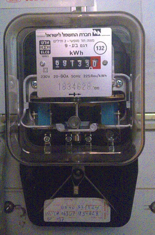
Our electric meter boxes connect single- and three-phase service, direct and CT metering, and different mounting arrangements. The technical topic below helps you describe these details to our team, whether the project concerns a new installation, door or enclosure replacement, or access for maintenance. A photograph of accessible identification can be useful when discussing an existing unit.
In this guide, we explain how to approach a new meter enclosure, replacement part, complete box replacement or change of location. We help you connect the equipment requirement to the meter, mounting and cable interfaces that shape the project.
Our control guidance explains the process behind the hardware
A control system connects a measured condition with an action. Our automatic-control topic explains the roles of sensors, feedback, controllers and actuators, using those relationships to make the operating task clearer before equipment is selected.
We use the process sequence and signal information to connect this task to the cabinet layout. An input/output list relates field devices to terminals; the operating sequence explains what should happen as conditions change. Our industrial automation content develops these system interfaces, while our control cabinets bring power, signals and devices into a practical assembly.
We use control principles to connect your operating goal with the sensors, actuators, power and cabinet interfaces a project needs. Understanding how a process is measured and influenced makes hardware discussions more precise, whether the task is a timed sequence or a continuous feedback loop.
We help connect equipment details with installation planning
Equipment has to fit both electrically and physically. Our installation topic brings the supply, location, cable route, mounting and access into one discussion. It helps your project team connect the equipment layout to the work that takes place on site.
We coordinate the selected equipment's dimensions and connection information with your installer or designer. Door movement, cooling space and terminal access can affect the surrounding layout as much as the overall cabinet size. Qualified personnel carry out installation and energization using the relevant equipment instructions and site procedures.
We help connect the equipment you order with the space, power connections and operating task at your site. By discussing these details with your designated project team, we can align our equipment configuration, drawings and delivery information with the installation plan.
Our ZFSG three-phase isolation transformer range contains 21 models. Separate windings provide galvanic isolation while matching voltage. The model table brings capacity and physical dimensions into the discussion alongside the load, frequency and installation.
ZFSO autotransformers: 3–500 kVA
Our ZFSO three-phase autotransformer range contains 23 models. The shared winding adapts voltage without galvanic isolation, giving it a different electrical role from an isolation transformer. We work through the required winding relationship before connecting capacity and construction to your application.
Our outline-drawing discussion adds orientation, mounting and connection access to the model-table dimensions, helping your team plan the equipment's position.
Explore our stabilizer and AC supply model ranges
Voltage regulation
Our ZFSBW compensated stabilizers include 14 models from 10–400 kVA. Our ZFLS oil-immersed stabilizers include 16 models from 100–3000 kVA. The incoming voltage range, operating cycle, cooling arrangement and available space connect the chosen capacity to its duty.
AC equipment and test supplies
Our ZFDP single-phase supplies include 11 models from 500 VA–45 kVA, and our ZFSP three-phase supplies include 11 models from 3–150 kVA. Input and output voltage, phase and frequency are considered separately. Continuous and transient load demand help us connect the model range with the equipment or test process.
Our project information supports each stage of the equipment
We coordinate the information your team needs around the selected model and project. The resources on this website support the first comparison; our subsequent technical discussion connects the required document set with the equipment's configuration and the stage of your project.
Information we coordinate with your equipment requirements
Information
What it connects
Project value
Electrical configuration
Supply, output, capacity and operating duty
A common equipment description
Outline and mounting drawing
Envelope, orientation, fixings and access
Space planning and installation fit
Connections and terminal schedule
Power, controls and field interfaces
Coordination with the surrounding system
Materials and components
Selected construction and fitted devices
Consistency between the requirement and design
Agreed inspection information
Equipment identity, check conditions and results
A reference for the order's acceptance process
Operation and care information
The supplied configuration and its use
Installation, operation and later parts discussions
We use drawings to coordinate fit and connections
Outline and mounting
We connect the equipment envelope with the mounting method, orientation, access and cable direction. A drawing can show the relationship between the installed equipment and the space around it, including doors, terminals and ventilation. This gives your team a clearer basis for planning the location.
Electrical and control interfaces
A one-line diagram describes the wider power arrangement; wiring and terminal schedules develop the connections inside and around the assembly. We use the appropriate drawing detail for the project stage and coordinate revisions as the configuration develops.
We relate material choices to duty and environment
Conductor size, magnetic-core characteristics and insulation influence a transformer's electrical and thermal design. Cabinet materials, finish, seals and fixings respond to exposure and mechanical demands. We connect these choices to the application's working conditions, then carry the selected construction into the equipment description.
For a cabinet in a dusty or corrosive area, enclosure construction and cooling need to be considered together. For a transformer, load behavior and operating temperature affect the winding discussion. Explaining the working environment helps us develop a more useful configuration than a material name alone.
Our manufacturing information explains how we build and check equipment
Our production equipment includes foil- and wire-winding machines, vacuum-pressure impregnation equipment and high-temperature ovens. Our electrical and thermal assessment equipment includes core-loss and interturn-withstand instruments, a high-current load platform, high-power AC test supplies and temperature monitoring.
We connect the checks and project records to the selected equipment and operating duty. Routine checks on a manufactured unit, design-related assessment and customer-witnessed activities serve different purposes, so we discuss their scope with the order. Our manufacturing and quality page explains the process and how our technical team supports it.
We keep project documents aligned with the configuration
A revised terminal position, component or enclosure dimension can affect several documents. We coordinate the drawing reference and revision with the electrical arrangement, outline and component information so both teams can work from the same equipment description.
Model and order references connect the final documents to the supplied equipment. They also make repeat orders, installation-layout discussions and replacement-part inquiries more precise. When your project changes, we can work through the affected interfaces and the information that needs to change with them.
Talk with us about the technical information you need
Tell us the product or application and what you want the information to help you do. You may be comparing models, planning an installation space or discussing a connection with your project team. A series or model reference is useful when available; we can also start with the equipment function.
Mention any drawing, nameplate photograph or existing document you would like to discuss. We can arrange a document exchange as we work through the configuration with you.