
Reactive Power Compensation Cabinets
We approach reactive power compensation around the way your facility operates. By connecting measured demand with source conditions, switching duty and cabinet layout, we help define a configuration that supports better use of the electrical supply.
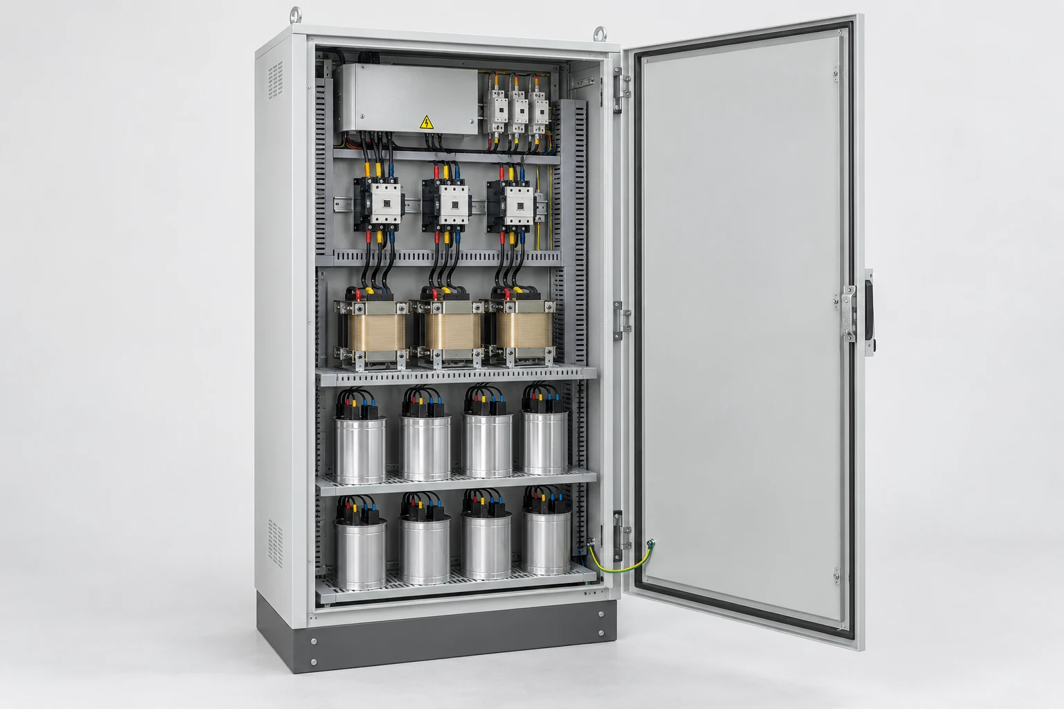
We coordinate the cabinet requirements with your project team. Compensation capacity, control functions and construction follow the selected application; cabinet supply, network studies and site activities are agreed as distinct parts of the project.
Put reactive power control to work for your facility
Motors, transformers and other inductive loads draw reactive power as part of their operation. Suitable local compensation can reduce the reactive current carried by upstream cables and transformers, improving capacity utilization at the supply point. We begin with the operational objective: managing a power-factor requirement, reducing reactive demand or accommodating a changed production load.
Connect the measurements to the objective
Active power in kW describes energy converted into work and heat; reactive power in kvar describes energy exchanged with electric and magnetic fields. Apparent power in kVA reflects supply loading. True power factor includes waveform distortion, while displacement power factor describes the fundamental voltage/current phase relationship. That distinction helps identify whether capacitor compensation addresses the main problem.
We discuss compensation when the objective concerns reactive demand or power factor, and voltage stabilization when the objective concerns incoming voltage variation. These functions address different conditions and cannot replace one another; the measured supply and load behavior show which function, or combination, belongs in the project.
Match compensation to the complete production cycle
We use the load profile to connect the cabinet discussion to real operating conditions. Full production, standby periods and equipment startups can produce very different reactive demand. A representative record helps establish the useful compensation range and the size of changes the controller must follow.
| Operating information | Configuration decision |
|---|---|
| Measurement point and CT arrangement | Which feeders and loads the control signal represents |
| Voltage, frequency and source mode | Electrical duty and source-dependent behavior |
| kW, kvar, kVA and power-factor trends | Compensation range and operating objective |
| Minimum load, peaks and process timing | Stage sizes, switching frequency and light-load response |
| Current and voltage harmonics | Interaction with the network and any reactor requirements |
Coordinate the cabinet with each supply mode
A compensation cabinet operates within a wider distribution system. We relate its connection point to the upstream transformer, protective devices, existing capacitor banks and downstream loads. Transformer kVA describes source capacity; the measured reactive demand determines the compensation discussion.
Existing banks and alternative sources
Existing stages may already respond to part of the load. Coordinating their locations and controls helps avoid competing actions. Generator supply, inverter operation, export and islanded operation also change the system conditions. We include those modes and their status signals in the configuration brief so the project team can define appropriate operation during a source change.
Choose compensation steps that follow the load
The pattern of demand matters as much as its peak value. We compare arrangements against the time scale of the process, the smallest useful correction and the switching duty. During light-load periods, excessive connected capacitance can produce overcompensation, so the minimum operating condition remains part of the selection.
| Load behavior | Arrangement to consider | Key consideration |
|---|---|---|
| Relatively steady demand | Fixed compensation associated with the load | Behavior when that load stops |
| Changing production demand | Capacitor-duty contactor-switched stages where the load cycle suits them | Stage sizes, switching frequency, discharge and re-energization constraints |
| Rapidly cycling demand | Thyristor-switched stages where rapid response is required | Required response, switching duty, heat removal and coordination with the selected capacitor system |
We compare these switching approaches using the load-change interval, acceptable correction response, expected number of switching operations and the selected capacitor system's discharge and re-energization requirements. Contactors provide mechanical switching; thyristors use semiconductor switching and introduce their own loss and thermal considerations. The equipment selection and quotation define the arrangement for the project.
Account for harmonics and network resonance
Capacitors interact with the network's inductive impedance. Together they can create resonant conditions that increase electrical stress at particular frequencies. Drives, rectifiers and UPS equipment therefore influence compensation choices through their current waveforms as well as their demand.
The role of a series reactor
A detuned arrangement pairs a capacitor with a selected reactor to change the branch's frequency response and manage resonance risk. It is not a universal harmonic filter. We keep reactive-power correction and harmonic-performance objectives distinct, using the project study to define the arrangement and the source configurations it must accommodate.
Connect feedback, switching and operating indications
The controller needs a feedback signal that represents the intended loads. We discuss CT location, sensing interfaces and source-status signals alongside the stage arrangement. This connects what the controller measures with what the cabinet can change.
Make operating states understandable
The configuration also addresses unavailable stages, temperature alarms, loss of feedback and reconnection behavior. Local indications and supervisory signals can then be defined around the facility's operating needs. Capacitors, reactors where used, switching devices, protection and discharge components each have a distinct duty in the coordinated schematic.
Build material and cooling choices into the layout
We bring component construction, cabinet materials and service space into the discussion before settling the enclosure dimensions. Capacitor temperature limits, reactor insulation and heat release, conductor joints and ventilation paths all influence the internal arrangement.
Materials and connection details
Copper and aluminum conductors differ in conductivity, dimensions and termination requirements; the comparison belongs to the complete current path. Enclosure material and finish address site exposure, while insulating supports and barriers organize separation and access. Cooling layouts need clear inlet and exhaust paths, accessible filters where fitted, and room around heat-producing parts. Our cabinet cooling page explains the thermal choices.
Make inspection and maintenance access practical
A useful cabinet layout keeps operating indications visible and allows planned access to replaceable components. We consider door movement, cable entry, component identification and the space needed to inspect connections alongside the protection and isolation arrangement.
Respect stored energy during service
Capacitors can retain energy after the incoming supply is isolated. Intrusive work requires qualified personnel following the equipment's isolation, discharge and verification procedures. For routine operation, clear labels and alarm descriptions help staff report a problem without entering capacitor compartments. Maintenance planning follows the selected components and the site's dust, heat and operating duty.
Evaluate performance under comparable conditions
We align the project discussion around a defined measurement point, operating load, source mode and recording interval. This makes the intended result measurable and helps distinguish compensation behavior from changes in production.
Agreed checks can cover stage response, feedback, indications and protective functions within the selected scope. Drawings, component references and operating settings keep those checks tied to the final configuration. Before-and-after power-factor measurements are most useful when their load conditions are comparable. Any cost assessment also depends on the site's tariff and operating pattern, rather than a fixed saving assigned to every cabinet.
Discuss your load and compensation objective with us
Start with your facility's main loads, present power-factor readings and the improvement you want to achieve. We can organize the configuration discussion from that overview, then bring in the connection point, existing banks, source modes and environmental constraints as the project develops.
The agreed configuration brings together the component schedule, drawings, operating information and relevant checks. Keeping those records with alarm and production-change history makes later maintenance and expansion decisions clearer. For connected equipment, explore our distribution cabinets and voltage stabilizers.