
Our Electrical Junction Boxes
We configure local connection enclosures around the cables and terminals your project needs. Lighting, control and power connections guide the box layout, usable space, cable entries and access, bringing the electrical connection and its physical installation together.
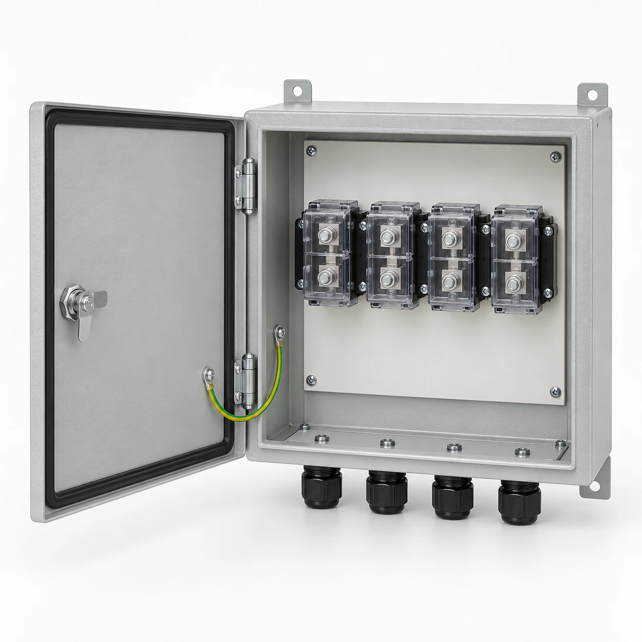
Our junction-box discussions combine enclosure construction with the agreed terminal, entry-fitting and mounting requirements. Your circuit and location information helps us develop a practical connection layout.
Local Connections for Lighting, Control and Power
Lighting connections
We start with the fixture, driver and supply cables, including any control connection. Their positions and cable routes help establish where the junction should sit and how the cover remains accessible after installation.
Control and power connections
Signal and power circuits can need different terminal arrangements, shielding or separation. We use the circuit functions to organize the layout and identify the bonding provisions specified for the installation.
For a wider cable distribution arrangement, explore our cable branch boxes. For assemblies with outgoing circuit protection, see our distribution cabinets. The connection purpose guides the equipment configuration.
Enclosure, Terminals and Connection Components
Connection path: upstream source and protection → junction terminals or selected connectors → outgoing load cable.
We define the project assembly through its body, cover, mounting hardware, terminals, bonding provisions, labels and entry fittings. Some projects need an enclosure prepared for site-supplied components; others require an agreed terminal arrangement within the box.
Where a protective device forms part of the local assembly, its model, mounting and connections join the layout. Identifying upstream protection and the components inside the box gives the electrical team a clear connection boundary.
Connection Space and Fixture-Support Requirements
A connection box provides room for specified conductors and terminals. Where it also supports a light fitting or other device, that mechanical duty becomes a separate design requirement. The fixture mass, attachment method and supporting structure all affect the arrangement.
We coordinate the box mounting interface with the selected support details. Shape, depth or material alone does not establish a permissible supported load. Cover trims and gap-covering accessories also serve a different purpose from structural supports. Describing the actual fixture and its mounting position helps the project team select the correct construction.
Conductors, Terminals and Cable Entries
We connect each circuit identifier with its terminal group and entry position. This keeps the electrical schedule and mechanical layout working from the same information.
| Group | Configuration inputs |
|---|---|
| Circuit | Identifier, function, voltage and load or signal type |
| Conductors | Quantity, metal, AWG/kcmil or mm² size and termination method |
| Terminals | Quantity, ratings, conductor compatibility and spare positions |
| Entries | Cable outside diameter, direction, entry identifier, thread and fitting |
| Additional provisions | Grounding or bonding, shielding and circuit separation |
Unused openings and their closures belong on the entry schedule so the completed arrangement is clear.
Usable Internal Space and Cable Bends
We assess working space after terminal rails, connectors, bonding provisions and cover intrusions are included. External width and depth describe the enclosure footprint; the populated layout shows the room available for conductor routing and access.
Space relationships: E1 incoming entry → B1 incoming cable bend space → T1 terminal group → B2 outgoing cable bend space → E2 outgoing entry.
The access envelope also includes the removable cover and room for the required tools.
Cable dimensions, connector geometry and the applicable installation requirements determine the needed occupancy and bending space. Their relationship to the terminal position can make a different enclosure proportion more useful than simply increasing its overall size.
Materials, Covers and Mounting Formats
We discuss material, thickness and finish in relation to the installation. Metal construction can provide rigidity and a durable mounting structure, with surface protection and bonding considered together. Nonmetallic construction brings different insulation and weight characteristics; environmental and mechanical conditions guide the material choice.
The cover, fasteners and gasket form a working assembly. Seal profile, compression and fastening positions affect fit, while finish and color address the appearance requirements. We keep these details connected to the chosen construction.
Surface mounting needs projection and cable-route clearance. Recessed mounting also depends on the opening, wall depth and finished-surface position. Mounting-hole coordinates and the supporting surface complete the dimensional discussion.
Cable Fittings and Environmental Conditions
Entry direction and location affect both routing and installation access. We coordinate cable diameter ranges, thread forms and the selected gland, hub or conduit fitting with the enclosure drawing. Factory openings and any planned site entry work are identified separately.
Indoor, outdoor, sun-exposed, humid, corrosive or washdown conditions place different demands on materials and sealing. Cover seals, fittings and unused-entry closures need to work as an assembled arrangement for the specified environmental protection. A changed fitting or opening can affect that result. Hazardous locations bring dedicated classification and equipment requirements for the project's specialist design team.
Our Connection Layout and Project Documents
We bring the outline, entry positions, terminal map and component references together in the agreed drawing package. Matching circuit and entry labels helps the installation team relate the equipment to the project schedule.
When a cable route, terminal group or fitting changes, the affected dimensions, labels and component list need to change with it. Keeping one coordinated revision supports manufacture, delivery and installation planning.
Delivery information identifies the supplied assembly and accessories, including covers, seals, closures and relevant equipment instructions. The receiving team can compare quantities and visible condition with the order; professional installers handle connection work and the required electrical inspection.
Cover Access and Replacement Parts
We consider cover removal before surrounding walls, furniture or adjacent equipment restrict the location. The layout needs space to reach fasteners, remove the cover and approach the connection area under the appropriate electrical work procedure.
Cover, seal, fastener, terminal and entry-fitting references help later replacement match the installed assembly. Overall dimensions alone may not capture differences in sealing profile or attachment details. Visible damage, a loose cover, moisture or a damaged external fitting should be reported through the site's maintenance process, with opening and electrical checks handled by qualified personnel.
Discuss Your Junction Box Layout
Tell us the connection count, cable sizes, terminal requirements and installation location. Add available entry positions, mounting dimensions and any fixture-support requirement. We can begin with those details and develop the enclosure configuration with your team.
Include quantity, destination and timing when available. Our installation planning resources explain how equipment dimensions and project documents connect with site preparation and delivery.