We bring power conversion, cabinets and metering together around the way your equipment works. From adapting a machine to its supply to arranging power and control connections, we connect the electrical requirement with the practical installation.
Explore our five application topics below. The related product and model links connect each application with our equipment ranges.
No matching topic. Try a broader term or
Our equipment connects the supply to the task
A machine, a control system and a metering installation use power in different ways. We start with that function and connect the incoming supply to the equipment it serves. Voltage, frequency, phase and operating demand shape the choice; space, cable direction and access then shape the installation.
Your application and our equipment approach
Application need
Our equipment's role
Explore the application
Connect machinery to a different voltage
Voltage adaptation with the required winding relationship
Our transformers adapt power for industrial equipment
We connect the supply and machine requirements through the transformer winding arrangement. Separate windings provide galvanic isolation; a shared winding provides voltage conversion where that isolation is unnecessary. Our ZFSG isolation transformers and ZFSO autotransformers give you two model ranges to explore.
Capacity that follows the operating cycle
Continuous demand, motor starts and repeated switching affect the load the transformer serves. We consider these conditions with the source voltage, phase and frequency, then coordinate terminals, cooling and the available installation space. The upstream protective equipment and downstream machine remain part of the same configuration discussion.
For export machinery, voltage adaptation can include 480 V to 380 V or 600 V to 380 V. A transformer retains the incoming frequency; when the machine also needs frequency conversion, our AC power supplies address that separate function.
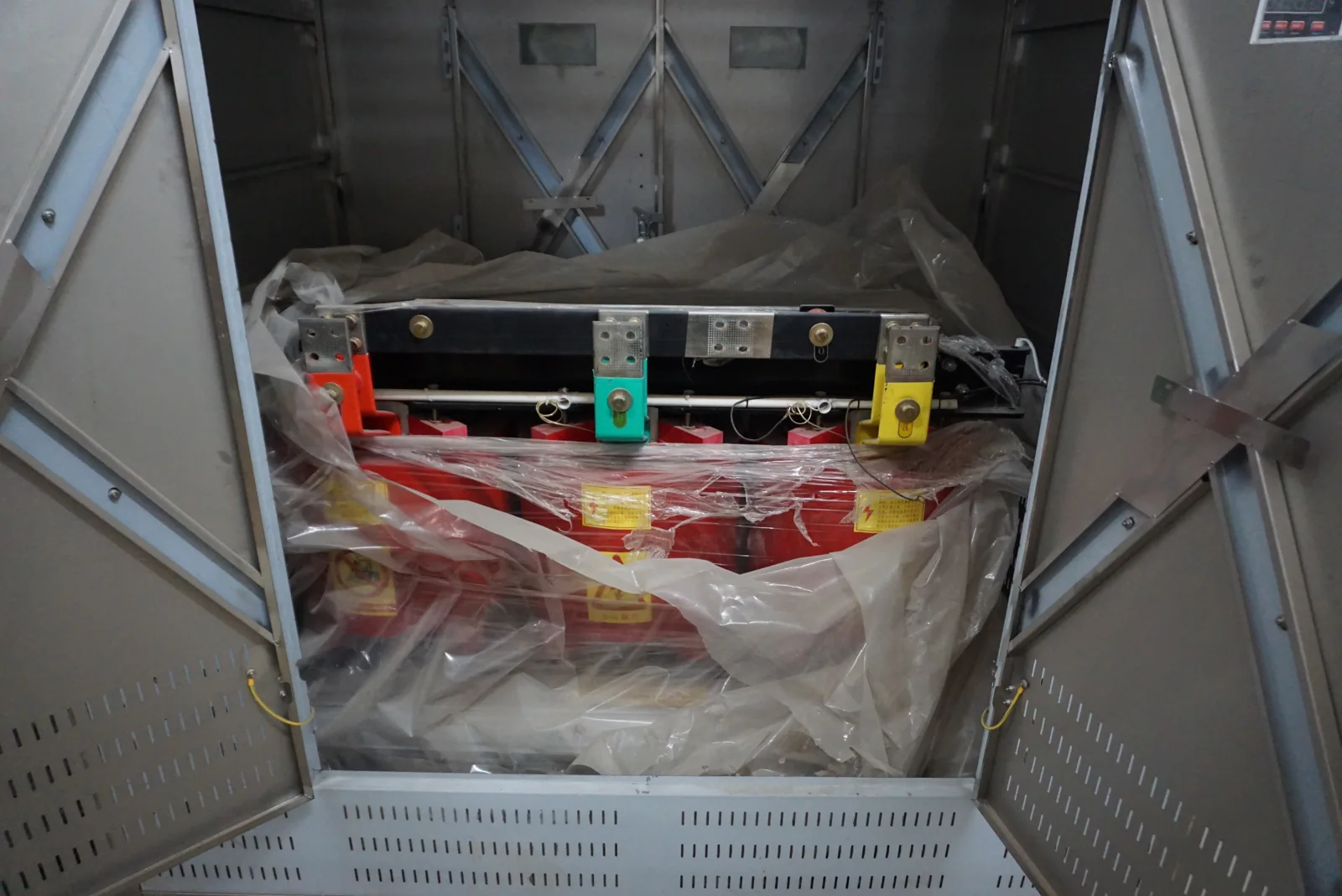
Transformer and cabinet integration brings the power-conversion equipment into the machine's electrical layout.
We match industrial machinery to the available site supply. Our transformer configurations connect the machine's voltage and load requirements with the winding arrangement, control power and installation layout, helping your equipment and electrical teams work from the same power-interface plan.
Our stabilizers and AC supplies address different power needs
Voltage regulation for a changing supply
Our voltage stabilizers respond to incoming voltage variation. We connect the observed supply range with the load's operating demand, including starts and long running periods. The ZFSBW compensated and ZFLS oil-immersed ranges bring different construction and cooling arrangements into that choice.
AC output for equipment and testing
Our AC power supplies provide equipment with the required voltage and frequency output. We consider steady operating points, startup demand and test transitions with the load. Explore ZFDP single-phase and ZFSP three-phase supplies. Input and output are separate configuration choices, while a motor-drive project focuses on the motor's speed and torque behavior.
Our transformer interfaces support solar and storage equipment
Solar and storage equipment connects a converter's output to the wider electrical network. We work through the transformer arrangement using the inverter requirements, power flow, operating modes and installation conditions. Voltage matching and winding relationships connect the converter to the system around it.
Electrical design with room for the installation
Converter characteristics, grounding, protection and thermal duty are considered with the project designer. We coordinate the transformer terminals, enclosure and access with the surrounding inverter and distribution equipment. This joins the electrical interface to the cable route, available footprint and service space, while the battery, converter and network teams develop their own parts of the system.
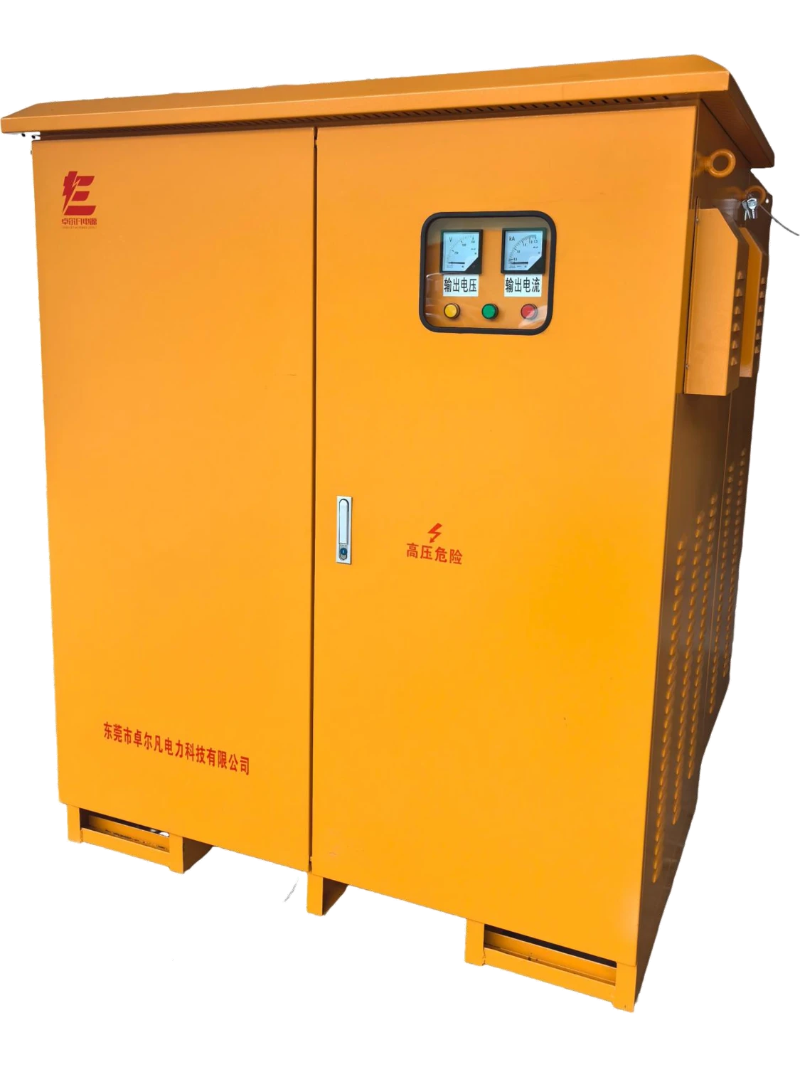
Enclosed transformer for project power interfaces.
We work with photovoltaic and energy storage project teams to configure the transformer interface between converters and the AC system. Inverter or PCS requirements, power-flow patterns and site conditions guide our discussion of windings, capacity, thermal duty and installation.
Our cabinets bring power, controls and connections together
We develop the cabinet around its contents: the incoming supply, outgoing loads, protective devices and control interfaces. Our distribution cabinets organize circuits, while our control cabinets connect devices and field signals to the operating sequence. An enclosure and a fitted assembly begin with different internal-layout needs.
Material, finish and construction respond to the environment. Panel stiffness supports doors and fitted equipment; seals and cable entries shape environmental separation; component spacing affects wiring and access. We consider heat dissipation alongside these details. Our cabinet cooling content explains how airflow, surrounding conditions and service access work together.
Our meter boxes fit the service and meter arrangement
Our electric meter boxes organize meter positions, cable connections and access around the service format. We work with the meter interface, number of accounts and mounting location so the enclosure supports installation and ongoing use. The serving utility's arrangement helps shape the meter position, sealing provisions and access.
Direct metering, meter-main combinations and CT metering cabinets connect different equipment inside the enclosure. A current transformer provides a measurement input, while a power transformer supplies a load. Keeping those roles clear helps us coordinate meter compartments, terminal space and the connections to the surrounding distribution system.
We coordinate cabinet and power interfaces for station systems
Station equipment brings auxiliary power, measurement, protection and supervisory signals into a shared electrical environment. We focus the cabinet and power-equipment discussion on those interfaces, working with the station team and the selected protection and control devices.
From device signals to a practical cabinet layout
Operating voltage, signal types, terminal allocation and communication connections shape the internal arrangement. Cable segregation, accessible terminal groups and clear identification help the site team connect the cabinet to field equipment. We use the one-line diagram and signal schedule to keep power circuits, indications and local or remote commands aligned with the wider station design.
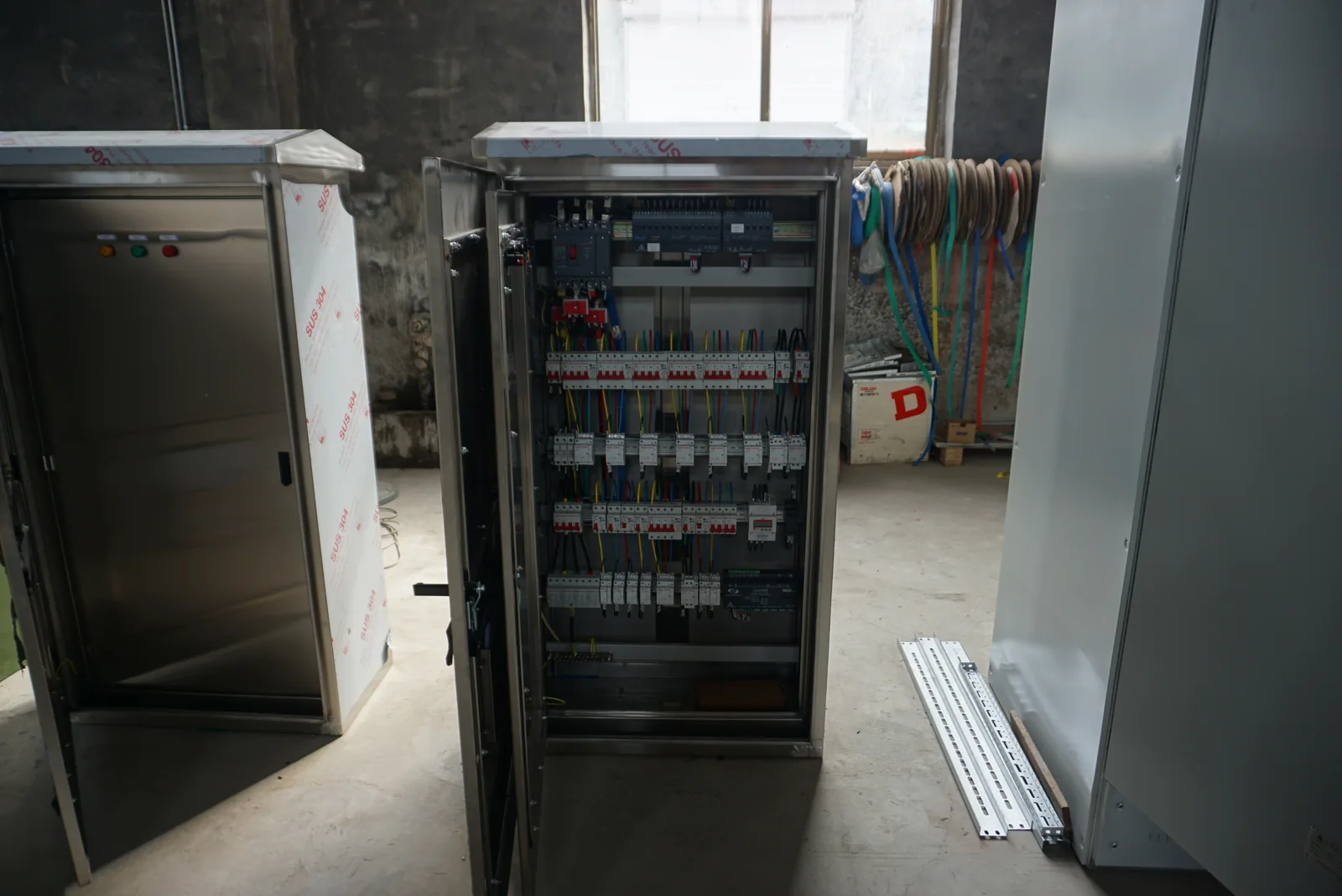
Internal equipment and terminal organization are central to control-cabinet layout.
We work with your project team to connect SCADA cabinet requirements with field devices, auxiliary power and the supervisory system. Our cabinet and power-equipment discussions bring signal functions, terminal arrangements and physical layout together, making the interfaces clearer from the first equipment brief.
Our control cabinets connect the process to its devices
A useful automation layout follows the process: what is measured, which action changes it and what the operator needs to see. We work with the operating sequence and field-device information to arrange the controller, terminals, switching equipment and power connections inside the cabinet.
Normal operation, stopping and recovery from an interruption place different demands on the control arrangement. We coordinate those interfaces with the machine or process team, including the separately defined safety functions. For driven equipment, our motor-control cabinet discussion also brings motor starting, acceleration, duty and cabinet heat into the layout.
We help connect automation goals with the power and cabinet equipment a process needs. Working with your machine and integration teams, we organize operating sequences, field signals and electrical interfaces so the hardware configuration follows the way the process is intended to run.
Our cabinet interfaces connect transport control equipment
Traffic and railway applications bring power, controllers, communications and field connections into a cabinet that must suit its location. We work on the enclosure, auxiliary-power and terminal interfaces alongside the project's signaling or traffic-system team.
Controller format, backup-power connections, cable entry and maintenance access shape the cabinet arrangement. Outdoor exposure also affects the finish, sealing and thermal design. We use the project's equipment and authority requirements to coordinate these details with the specified system, keeping the cabinet's construction and connections useful to the people installing and maintaining it.
We work through cabinet and power-interface requirements with traffic and railway project teams. The selected control equipment, field circuits and installation environment guide the enclosure, terminal and auxiliary-power arrangement, keeping our cabinet work connected to the project's technical requirements.
Our project cooperation connects the equipment and site teams
We work with your machine builder, system designer or site team to connect our equipment to the wider project. The conversation moves from the application to the selected configuration, then to drawings, manufacturing details and delivery preparation. The agreed scope brings those contributions together.
How we develop the equipment requirement with you
Project stage
What we work through together
Value for your team
Application
Supply, load, operating task and installation
A clear equipment function
Configuration
Winding, devices, enclosure and connections
Electrical and physical choices developed together
Drawings
Envelope, terminals, signals and revisions
A shared reference for equipment interfaces
Preparation and handover
Checks, identification, packing and documents
Information for receiving and installation planning
We use project information to connect design and installation
Electrical relationships
A one-line diagram shows the source, conversion equipment and loads. A connection drawing or signal schedule adds the detail around terminals and controls. We use these documents to relate the equipment configuration to the system it serves, including the relevant voltage, current and operating conditions.
Physical fit and handover
An outline drawing connects equipment dimensions with mounting, cable access, ventilation and the space needed to operate or maintain it. We coordinate drawing revisions with the agreed inspection and document requirements so the information follows the selected equipment through delivery. Our technical resources bring model information and project-document topics together for the next conversation.
Discuss your application with our team
Tell us what you need to power, control or meter, together with the supply and load details you already know. We can work through the transformer, stabilizer, AC supply or cabinet arrangement with you. A product model is helpful if you have one, but the application is enough to begin.
The destination, quantity and available space help us focus on the practical configuration. If you have a nameplate photograph, equipment list or drawing, mention it so we can arrange a document exchange during the follow-up.