
Meter-Main Combination Panels
We coordinate meter-main configurations that bring the metering section, main device and outgoing connections into a clear layout. Our project approach links these electrical functions with the enclosure, cable routes and access needed at the installation.
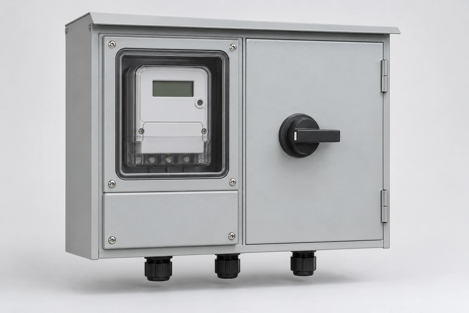
We define the selected devices, compartment arrangement and project service requirements together with your team. The configuration can connect to separate downstream distribution or incorporate the agreed branch-circuit section.
Our layout gives each function a defined space
Metering section
We coordinate the selected socket or meter mounting arrangement with reading access, connection space and the utility's sealing area. The meter reference defines the interface around which this section is organized.
Main-device section
The main device provides the specified disconnection or protective function. A switch performs its switching duty; overcurrent protection requires the corresponding protective device. We consider device count, operating access and terminals in the section layout.
Outgoing section
We connect the main section to the required outgoing arrangement, whether it serves a separate board or an integrated group of branch circuits. Keeping these functions clear helps align the physical assembly with the project one-line diagram.
We align the metering arrangement with the service design
We work from the service voltage, phase, conductor arrangement and frequency together with the selected meter interface. The project's utility drawing establishes the meter and disconnect sequence, retention details and any bypass or sealing provisions.
We bring that arrangement into the cabinet layout with the customer and utility access areas identified. Where the project uses the assembly as service equipment, we coordinate the applicable requirements in the configuration discussion. This connects the enclosure and device selection to the intended installation rather than relying on a category name alone.
Each electrical rating has a different role in the configuration
We consider the socket, bus, main device and complete assembly as related but distinct parts of the design. Their ratings describe different duties, so they remain separate fields in the equipment schedule.
| Design area | Role in the configuration |
|---|---|
| Meter socket | Service or continuous-current duty under its specified conditions |
| Main device | Device current rating, poles and number of disconnects |
| Bus | Current-carrying arrangement within the selected assembly |
| Protective device | Interrupting duty at the operating voltage |
| Complete assembly | Fault-current duty with the specified protective-device conditions |
We use these relationships to coordinate the components with the actual service and load requirements.
We compare separate distribution with integrated branches
The outgoing arrangement influences cabinet size, terminals and maintenance access. We discuss the downstream equipment with your team so the selected layout serves the intended circuits.
| Arrangement | Connection relationship | Layout focus |
|---|---|---|
| Separate distribution | Meter and main sections connect through the specified outgoing interface to a separate board | Outgoing terminals, cable route and downstream board location |
| Integrated distribution | Meter and main sections connect to a distribution area within the assembly | Branch devices, internal bus arrangement and circuit access |
Any feed-through provision is defined with its position and protection relationship. For several accounts, our multi-meter enclosures content addresses the additional meter-position and outgoing-supply relationships.
Our circuit schedule connects loads, devices and spare positions
We organize the outgoing circuits by their served load, poles, required ratings and terminal interfaces. The device schedule connects those circuits to the selected breaker family and its permitted use in the assembly.
Spare physical positions and spare electrical capacity serve different purposes. An empty position creates room for a device; future load also needs capacity in the supply and associated components. We discuss expansion in both terms, keeping the proposed load, protective-device combination and enclosure space together. This also provides a useful reference for later configuration or replacement enquiries.
We coordinate fault-current duty with the system conditions
Normal load current determines one part of the equipment duty; prospective fault current determines another. We use the available fault-current information from the project utility or designer to align the assembly and protective devices at the actual operating voltage.
Where a rating depends on a particular upstream device or device combination, that relationship stays with the selected configuration. We consider it alongside the bus and outgoing arrangement. The resulting equipment schedule connects component choice to the complete assembly, with the relevant project electrical conditions kept visible throughout the discussion.
We organize neutral interfaces and access boundaries
Our layout coordinates the neutral terminals, bonding provisions and compartment divisions with the project's electrical design. The position of each connection needs to work with the incoming and outgoing conductors as well as the devices inside.
We also align utility sealing areas with the controls intended for ordinary operation. Metering sections and service-side connections retain their designated access and isolation requirements, even when a main handle is accessible. Meter handling and sealed areas belong to the authorized utility parties; qualified personnel carry out electrical installation and internal service.
Our enclosure choices support connections and practical access
We consider overhead or underground feed, conductor details and outgoing cable routes when arranging entries and terminals. Terminal material compatibility and size range follow the selected conductors; cable bends, device spacing and heat-producing components shape the usable internal layout.
Panel material and structure support the mounted equipment, while the selected finish responds to corrosion and environmental exposure. Doors, gaskets, meter openings and fittings complete the enclosure. We coordinate these choices with mounting and maintenance access. Our outdoor meter boxes content develops exposure considerations, and our meter-box range covers the wider enclosure configurations.
Our drawings and documents keep the configuration consistent
We connect the general arrangement, one-line diagram, component schedule and terminal information around the agreed equipment configuration. Model and circuit identification then relate the physical assembly to those documents.
Our project discussions include the utility interface, selected device combinations and the dimensional or functional checks relevant to the order. The manufacturing and quality process links these checks to the equipment's duty. When a configuration changes, we coordinate the affected drawings and component references so both teams continue from the same design basis.
We coordinate delivery and future equipment enquiries
We discuss packed dimensions, gross weight and protection for the meter interface, main device and enclosure doors as part of the delivery scope. Package identification and the component schedule help connect the shipment to the project order.
Operating information identifies the intended controls and relevant equipment references. For later breaker, accessory or enclosure enquiries, those references help us consider the replacement in the context of the installed assembly. We agree the requested parts and document scope with your team, supporting clear communication between equipment supply and the site's installation or maintenance work.
Discuss your meter-main configuration with us
Start with the meter interface, number of main devices, outgoing arrangement and quantity. Tell us whether the project connects to a separate distribution board or needs branch circuits within the assembly.
We can then work through the service details, circuit schedule, available fault-current information and installation space together. If you already have a one-line or utility drawing, mention its reference so the next conversation can focus on the remaining layout and component decisions.