
Industrial Control Cabinets
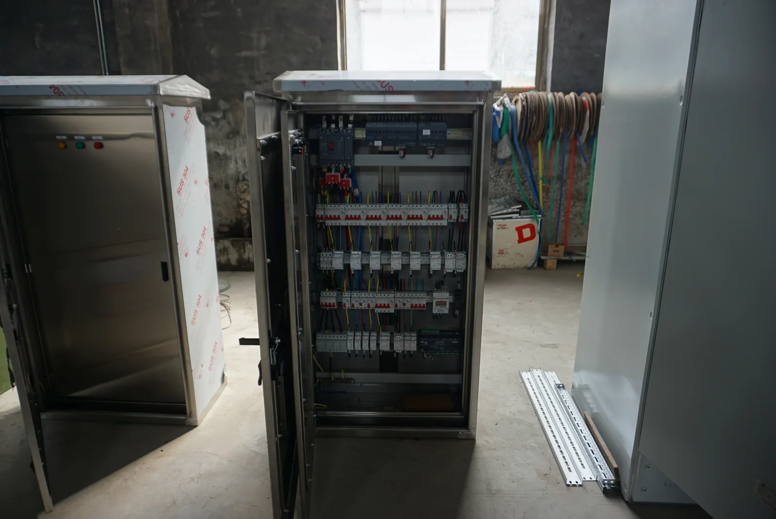
Our industrial control cabinets connect machine functions with an organized hardware layout. We work through power, control devices, I/O and field terminals together, giving your equipment team a clear connection between the operating requirement and the cabinet's physical arrangement.
A cabinet structure suited to the control task
Machines use different control arrangements. Relay logic can serve defined switching functions, a PLC can coordinate programmable sequences, and remote I/O can gather field signals around a network connection. We discuss the structure from the machine's functions and interfaces; a control cabinet does not need a PLC simply because it contains control equipment.
Our focus here is the physical cabinet: enclosure, mounted devices, internal connections, identification and the agreed equipment information. The automation systems page develops process behavior, while our control principles guide explains feedback and control terminology. Keeping these views connected helps turn a machine requirement into a useful hardware configuration.
Power, logic and field connections in a coherent layout
Functional arrangement: incoming supply → control-power equipment → relay or controller functions → field terminals → sensors and actuators. Communications and operator interfaces connect to the relevant control devices. The arrangement describes functions; the wiring drawings define the circuits.
| Structure | Control role | Layout focus |
|---|---|---|
| Relay arrangement | Defined switching and interconnection functions | Device groups, contacts and traceable wiring |
| PLC-based arrangement | Programmable logic with connected inputs and outputs | Controller, modules, power and engineering interfaces |
| Remote I/O arrangement | Field signals connected to a wider control system | Network interface, local power and terminal grouping |
Separate incoming power from control-voltage needs
Incoming voltage, phases, frequency and source conditions establish the cabinet's power interface. The control devices may use different voltages from the main equipment. We organize these supply requirements separately so each device group has a clear source and connection path.
A control transformer supplies an AC control circuit; a DC load needs the appropriate DC conversion function. Coil pickup and electronic-device startup can affect that selection. The complete panel's short-circuit current rating, or SCCR, also belongs to the assembled configuration. We coordinate that requirement with the source and selected components rather than treating one device's rating as the whole panel rating.
Connect signal meaning to modules and terminals
| Function | Signal information | Physical reference |
|---|---|---|
| SENSOR_A — measurement | Signal type, range, units and invalid condition | Device, channel and terminal |
| STATUS_A — equipment state | Contact or data state and expected interpretation | Input, cable and circuit label |
| ACTUATOR_A — action request | Command interface, response and feedback | Output, terminal and receiving device |
We use the signal list to discuss module counts, terminal groups and spare channels. The same tag follows a point through the field-device information, I/O schedule and cabinet drawing. This makes the physical connection and its intended meaning easier to follow during installation and later fault investigation.
Signal conditioning and communication interfaces
Match the electrical signal to its destination
A sensor's output and a controller's input need compatible electrical characteristics. Signal conversion or isolation may be part of that interface. We discuss those requirements alongside the device information, keeping the field signal, conditioning function and I/O channel connected in the schedule.
Keep network data connected to device meaning
For networked equipment, protocol, device version and data mapping shape the interface. A matching connector does not establish that the receiving system interprets a value correctly. We coordinate the cabinet's mounting, power and connection needs with the project's integration information, while hardware brands and software functions follow the selected project arrangement.
Consistent identification from cable entry to device
Terminal groups provide the handoff between internal equipment and field wiring. We organize identifiers around circuit purpose, field-cable references and I/O tags. The terminal arrangement also takes account of conductor material, connection space and the distinction between cabinet wiring and site connections.
Power, control and communications routes have different interface requirements. Their grouping, shielding connections and bonding details belong in the layout with the selected devices. Coordinated labels help a technician follow a circuit without relying only on where a component sits. Cable-entry direction and room for termination work are therefore considered before the enclosure footprint is finalized.
Enclosure construction and the location of heat sources
Mechanical and environmental choices
Enclosure rigidity, mounting arrangements and door hardware support the installed equipment and service access. Material and finish choices respond to moisture, contaminants and cleaning conditions. We discuss these alongside the bonding arrangement, cable entries and operator-device positions so the enclosure works with its contents.
Heat, airflow and maintenance space
Power supplies, drives and other devices contribute different heat losses. Their position affects airflow and the temperature around neighboring controls. We consider the duty and heat path with filter or cooling-unit access, rather than assigning all remaining space to future hardware. Our cabinet cooling page develops this relationship between losses, environment and cooling configuration.
Our cabinet work within the wider machine project
Hardware needs an agreed relationship with application logic. We discuss the control narrative, device configuration and operator functions with the project's controls team, connecting the cabinet's physical interfaces to the intended machine behavior. Software versions and engineering-file references then stay associated with the selected devices.
Programming, licensing, machine-safety design and site integration are defined with the relevant project specialists. A normal control output and a safety function have different design responsibilities. Making that relationship clear once in the project plan allows the cabinet, application and field teams to coordinate their work without losing track of the equipment interfaces.
Configuration checks and documents for handover
We agree the cabinet checks and accompanying information around the selected configuration. Point identification, indications and command feedback can be connected to the control narrative. Normal operation, an invalid input and power recovery provide useful scenarios for developing the project's expected behavior and inspection scope.
The general arrangement, wiring diagrams, terminal and I/O schedules, component information and inspection records form a connected equipment package. Where configuration files are included, their versions are identified with the relevant hardware. Factory simulation and checks on the actual machine address different conditions and are coordinated through the project's installation and commissioning plan.
Tell us about your machine and field interfaces
Start with the machine function, available supply and an approximate I/O description. We can then discuss the control structure, field connections and cabinet environment with your team. An existing layout or signal list is helpful when available and can be exchanged as the configuration develops.
Quantity, destination, access restrictions and handling needs become part of delivery planning. For later changes, consistent component, terminal and configuration references help identify compatible replacements and affected circuits. Qualified personnel use the final documents for installation and maintenance, while operators can report the indicated fault and operating state through the equipment's normal support route.