
Fixed and Withdrawable Switchgear Configurations
We develop cabinet configurations around your circuit duty and access requirements. For switchgear projects, that means considering switching structures, busbars, terminals and controls together, so the arrangement supports both the electrical system and the planned approach to maintenance.
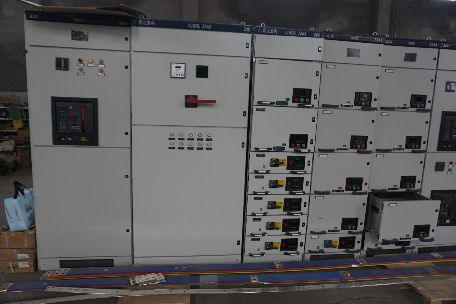
The switching structure follows the electrical system
Switchgear connects circuits, interrupts normal current and supports the system's protection functions. The cabinet structure brings devices, conductors, insulation and operating interfaces into an arrangement that fits the installation. We discuss that arrangement from the one-line diagram and the work the circuits need to perform.
Low-voltage and medium-voltage applications
Voltage class changes insulation requirements, clearances, equipment selection and the relevant assembly rules. Low-voltage distribution assemblies and medium-voltage metal-enclosed equipment therefore follow distinct configuration paths. We identify that path early with your project team, then develop the cabinet and interface requirements around the selected equipment and project standards. The equipment package is defined in the project quotation.
We also distinguish enclosure terminology from electrical performance. Metal-enclosed describes equipment within a metal enclosure; classifications such as metal-clad or armored involve defined construction and compartment arrangements under the applicable equipment standard. The classification and actual assembly determine which description fits. A metal enclosure or a metal-clad label alone does not establish internal-arc performance, so we keep the specified construction and any required fault-performance criteria separate in the configuration discussion.
Organize incoming circuits, bus sections and feeders
A one-line diagram shows how power moves through the installation; a circuit schedule gives each connection its purpose and duty. We use both to organize incoming sections, bus ties, transformer connections and outgoing feeders. Voltage, frequency, current and expected operating states stay connected to the corresponding circuit.
Multiple sources introduce further choices: which sources can be connected, where separation occurs and which functions depend on auxiliary power. These decisions influence compartment arrangement and control interfaces. Our distribution cabinet page develops outgoing circuit planning, while the switchgear configuration focuses on how the switching structure serves those circuits and the required maintenance access.
Fixed and withdrawable arrangements serve different access needs
| Feature | Fixed structure | Withdrawable structure |
|---|---|---|
| Device mounting | Device secured within the assembly | Device works with a matched cradle or carriage |
| Primary interface | Connections arranged for the installed device | Connection interfaces accommodate defined device positions |
| Auxiliary circuits | Control wiring follows the fixed layout | Auxiliary connectors and position functions need coordination |
| Replacement planning | Access to mounted equipment and connections | Compatible unit, handling space and removal route |
We compare these arrangements against the expected outage window, access direction and replacement strategy. A withdrawable structure can organize device removal, but its permitted service conditions depend on the complete equipment design; the structure alone does not determine an outage duration.
Position indications explain the device state
Conceptual position labels: connected | test | disconnected | removed. These labels describe states used in some withdrawable designs. They are a functional explanation, not a sequence for moving equipment.
Primary and auxiliary connections can differ
In a test position, a design may disconnect the primary power path while retaining auxiliary connections for control functions. A position indication therefore needs to communicate more than whether the device has moved. We include position signals and their meaning in the control-interface discussion. Device movement, testing and access remain subject to the specific equipment instructions, interlocks and authorized site procedures.
Current, fault duty and insulation describe different demands
| Duty | What it describes | Configuration relationship |
|---|---|---|
| Continuous current | Normal sustained electrical loading | Conductors, contacts, terminals and heat removal |
| Interrupting duty | Current a device can interrupt at the system voltage | Switching device and protective coordination |
| Short-circuit withstand | Assembly behavior under a specified fault duty | Bus system, supports and complete construction |
| Insulation duty | Electrical stresses associated with the voltage class | Clearances, insulation and equipment arrangement |
We coordinate these requirements with the selected devices and your system information. A circuit breaker's rating and a complete assembly rating describe different boundaries, so the cabinet discussion keeps both in view.
Busbars, terminals and cable space share one layout
Conductors and support construction
Copper or aluminum choices affect conductor dimensions, mass and connection arrangements. Bus supports and insulation also form part of the complete structure. We discuss these elements together with the required duty, rather than selecting a conductor material independently of its terminals and surrounding equipment.
Access and enclosure geometry
Front or rear access changes the space needed around the lineup. Cable approach, bending space, termination positions and door movement influence cabinet depth and compartment layout. We bring those interfaces into the arrangement discussion alongside enclosure material, finish and cooling. Moisture, dust and corrosive exposure then guide the construction choices for the actual location.
Connect device functions to local and remote control
Control power supports trip and close functions, indications and other configured auxiliaries. We organize those connections around the device functions and the project's operating modes. A command, permission, position signal and alarm have different meanings and are identified separately in the interface information.
Interlocks coordinate permitted actions; a remote indication reports a condition. Keeping the two roles distinct helps the controls team define communication-loss behavior and local authority. Our substation automation page covers supervisory signals in more detail. Protection studies and relay settings remain with the responsible project specialists, while the cabinet arrangement provides the agreed interfaces.
Project drawings and checks tied to the configuration
We bring the circuit arrangement, equipment identifiers, bus and terminal information and control functions into the agreed project document package. These records connect the one-line diagram to the physical layout and give installation teams a consistent set of references.
Inspection activities are defined around the selected assembly and project requirements. They can address equipment identification, configured indications and permitted interlock functions within the agreed test scope. Document revisions and component changes remain connected to the final build. This keeps the information useful for handover and later equipment work, instead of leaving a collection of unrelated device sheets.
Coordinate transport sections and site interfaces
A lineup may need transport sections that differ from its final operating arrangement. We discuss access restrictions, section dimensions and handling needs with your project team before the transport plan is settled. Clear section identification links the packing information to the installation layout.
Where field interfaces are present, the corresponding connection information accompanies the agreed equipment documentation. The site team plans receiving, assembly and commissioning around the final drawings and handling instructions. For equipment located within a larger package, the substation configuration page connects these decisions to foundations, compartment access and the wider installation.
Discuss your circuits and maintenance goals
Start with the one-line diagram or a short description of the incoming supply and outgoing circuits. Tell us how equipment is accessed and what your maintenance team needs to replace or inspect. We can then discuss structure, compartment layout and the information needed for the selected configuration.
Spare-device planning includes the device, cradle where used, mechanical coding and auxiliary connections. Matching only current or physical dimensions can miss an important interface. We keep these replacement considerations connected to the project equipment list, together with installation space, quantity and destination.