
Electrical Enclosure Materials and Cooling: One Cabinet, Three Environments
We hold the equipment and its assumed 140 W internal heat loss constant, then compare how dust, humidity and high ambient temperature change the enclosure decisions.
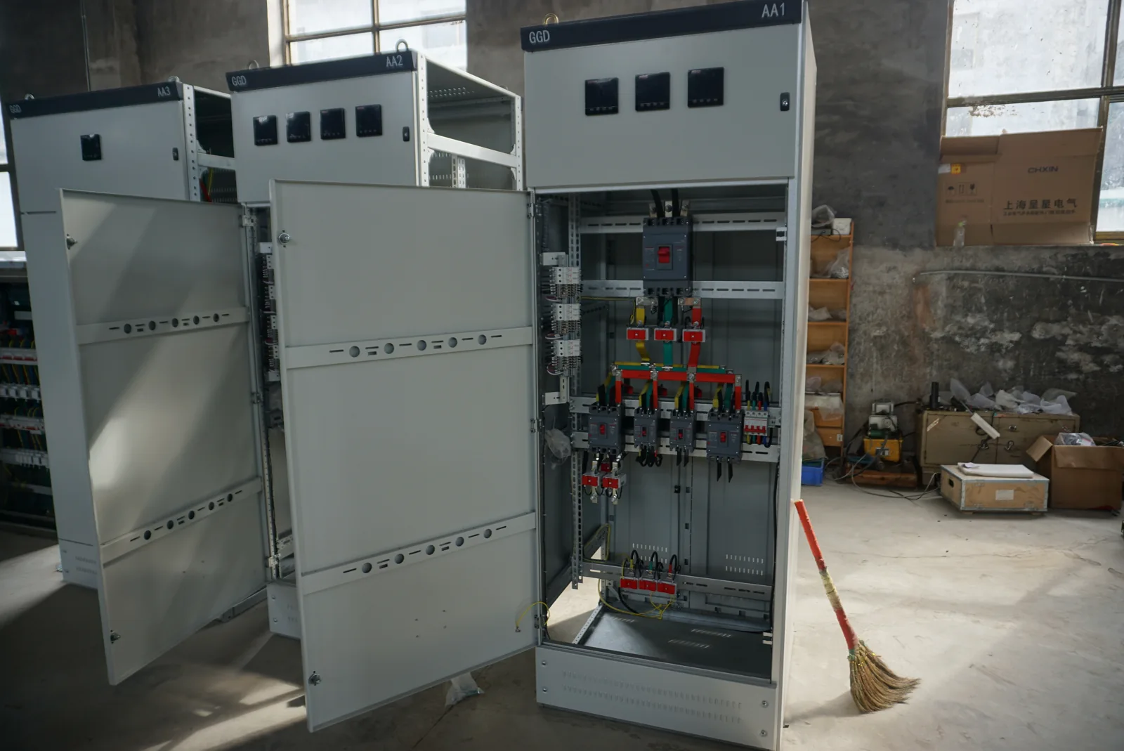
Compare three environments around the same equipment
We can change the right enclosure choice without changing the equipment inside it. To show how, we follow one hypothetical control cabinet through three possible locations. In every case, the assumed internal component losses total 140 W during the operating condition under discussion. The equipment list stays fixed; contamination, moisture and surrounding temperature change.
| Location scenario | Additional site information | Decision that changes |
|---|---|---|
| Dusty production area | Dust type and quantity, cleaning method, surrounding-air temperature, maintenance access | Whether exchanging ambient air is suitable and how filter condition affects airflow |
| Humid or intermittently wet area | Humidity cycle, cold surfaces, spray direction, cleaning chemistry and shutdown periods | Material/finish, sealing interfaces and condensation management |
| High-temperature location | Peak and continuous ambient temperature, radiant or solar heat, component temperature limits | Whether passive heat loss or ambient-air cooling can meet the required internal condition |
These are planning examples, not hazardous-area classifications or equipment ratings. We establish any special exposure classification separately. Our enclosure configuration page covers the available layout decisions; here we connect each decision to the same operating example.
Follow coating condition through the dusty and humid cases
We consider coated carbon steel when the mechanical layout, finish and exposure suit the application. The protective finish and its condition matter at cut edges, fasteners and modified openings as well as on broad panels. A clean indoor location and a wet area with aggressive cleaning present different coating demands.
In the dusty example, the first question is whether dust settles harmlessly on the outside or enters through cooling openings and collects on devices. Changing the panel material does not solve an unsuitable air-exchange path. We connect the finish choice to filter access, surface cleaning and the route through which heat leaves the cabinet.
In the humid example, we also consider water retention around horizontal surfaces, hardware and entries. The same coating designation does not define the performance of every altered door, gland or exposed edge. We coordinate the complete formed and finished assembly with the installation conditions.
Use stainless steel for a defined exposure, not as a cure for moisture
We compare stainless-steel construction against the actual contaminants, cleaning agents and maintenance conditions. Grade, surface finish, fabrication details and contact with other materials all affect the discussion. Stainless steel can be valuable in an appropriate corrosive environment, while salts, deposits and unsuitable cleaning can still create problems.
The 140 W heat load remains
Changing our illustrative cabinet to stainless steel does not remove its internal losses or prevent condensation on a cold surface. We still need to consider how heat moves through the construction and where water can form. The cooling approach, seals and component temperature limits remain separate design inputs.
We also discuss hinges, fasteners, mounting parts and contact surfaces as a connected materials system. This keeps a corrosion-focused panel choice from leaving an overlooked hardware or cleaning interface elsewhere in the cabinet.
Consider nonmetallic materials with their mounting and thermal interfaces
We consider nonmetallic enclosure materials in relation to corrosion exposure, impact, sunlight, temperature and the installed equipment load. Their lower mass or insulating structure can be useful, but the actual material and construction determine suitability. Door stiffness, fastening details and support for mounted components remain part of the mechanical design.
For our example, changing to a nonmetallic body changes the path through which the same 140 W can leave. The thermal behavior of the selected wall material and construction therefore belongs in the calculation; we do not assume the result will match a metal cabinet of the same outside size.
Metal mounting plates, devices and cable systems may still need protective-bonding arrangements. Electromagnetic shielding also follows the complete construction and equipment requirements. We discuss these interfaces with the electrical team instead of assuming an insulating shell settles every grounding or interference question.
Treat doors, gaskets and entries as one closure system
We trace every opening in the example cabinet: door perimeter, cable entries, cooling cutouts, viewing windows and service panels. Their location and fit affect how dust and moisture can reach the interior. Gasket material, compression, door alignment and the mating hardware work together.
Adding a filter fan changes both the heat path and the environmental interface. Adding a closed-loop cooling unit also introduces a mounting opening, mechanical load and its own sealing details. We therefore coordinate the selected equipment and cutout drawing before fixing the panel layout.
IP classifications and NEMA or UL enclosure Types use different assessment systems; we do not convert one directly into the other. The specified performance applies to a defined completed construction. Our accessory interface guide explains the hardware and entry details that help keep the selected configuration consistent.
Recalculate the same 140 W internal-loss budget
We calculate cabinet heat from the losses of components inside it at the relevant operating condition. The power delivered to a motor outside the cabinet is not all released as heat inside the enclosure. For an AC-to-DC supply, the conversion loss belongs in this internal budget; counting its entire DC output again as local heat would be incorrect unless that output is actually dissipated inside.
| Internal equipment group | Assumed dissipation | How we would replace the assumption in a project |
|---|---|---|
| Motor-drive electronics | 60 W | Loss data at the selected load, switching and operating conditions |
| AC-to-DC power supply | 25 W | Input/output efficiency or manufacturer loss information at the actual load |
| Control logic and relays | 15 W | Device dissipation and energized-state schedule |
| Other internal auxiliaries | 40 W | Identified loads, location and simultaneous operating state |
| Total internal loss | 140 W | 60 + 25 + 15 + 40 = 140 W |
All four values are illustrative. We keep solar or radiant heat and any other external heat gains in separate entries. Cabinet surface heat exchange also depends on temperature difference, area, material and installation. The 140 W sum is consequently an input to thermal selection, not a final cooling-unit rating.
Do not average away the critical operating period
If equipment cycles, we retain the peak duration and the off period as well as the average loss. The cabinet and components respond over time, so the appropriate assessment must follow the operating cycle and allowable temperatures.
Select a heat path for each environment
We first establish the allowed internal conditions and the surrounding air or cooling-medium conditions. A fan moves heat using air exchange; it does not refrigerate that air. An air-to-air heat exchanger separates internal and external air but still needs a suitable temperature difference. Refrigeration or a suitable water-based system introduces different operating conditions, utilities and maintenance needs.
| Same internal loss | Possible direction to assess | What must also be resolved |
|---|---|---|
| 140 W in a dusty location | Passive surface cooling, or filtered ventilation where the dust and air conditions allow it | Filter pressure drop, realistic airflow, contamination and access for cleaning or replacement |
| 140 W in a humid location | A suitable separated-air or other controlled thermal arrangement | Humidity, surfaces below dew point, seals and any condensate-management interface |
| 140 W with hot surrounding air | Cooling with adequate capacity at the actual hot-side condition if passive exchange is insufficient | Required internal temperature, external heat gains, utility conditions and the selected unit performance curve |
A temperature comparison before equipment sizing
As an illustrative constraint, suppose the surrounding air is 45 °C while the project requires the cabinet air to remain at or below 40 °C in steady operation. Ambient-air ventilation and a passive air-to-air exchanger cannot provide that below-ambient result on their own. We would assess an appropriate active or colder-medium heat-removal method, including its capacity at those conditions. These assumed temperatures do not define a rating for our cabinets or cooling equipment.
Our cabinet cooling page develops the method and performance inputs once this environmental comparison is established.
Keep condensation and service access in the same layout
We consider operating and shutdown conditions because condensation can occur when a surface becomes colder than the surrounding air's dew point. Cooling air more aggressively is not automatically a remedy for moisture. Opening a cold cabinet in humid air can also change the moisture exposure around its components.
For the humid version of our example, we coordinate the temperature-control strategy, selected equipment and any required condensate path with the project team. For the dusty version, filter access and the ability to inspect obstructed air paths take on greater importance. For the hot version, the external cooling equipment also needs an unobstructed heat-rejection path.
We reserve space for the actual door movement, filter withdrawal, cooling-unit removal and cable access shown in the chosen layout. These dimensions follow the selected components and site arrangement; a nominal empty cabinet footprint does not describe the full service envelope.
Turn the comparison into a usable cabinet brief
We bring the example together in four groups of project information: the component-loss schedule, environmental conditions, enclosure and mounting geometry, and service-access requirements. The same electronics can lead to different material, sealing and cooling choices when any one of those groups changes.
For your project, share the equipment list and known losses, expected simultaneous operation, indoor or outdoor location, contaminants, temperature and humidity conditions. Add cable direction, available space and cleaning arrangements. We can then discuss a coordinated enclosure layout with your team and connect it to the control-cabinet hardware configuration.
If the installation location changes later, we revisit the affected inputs before carrying over the original configuration. That creates a useful record of why a material or cooling method was selected.