
Voltage Stabilizer vs Frequency Converter: Which Function Do You Need?
We compare four power functions through two practical examples: an imported machine with a supply mismatch and a test station that needs different AC operating points.
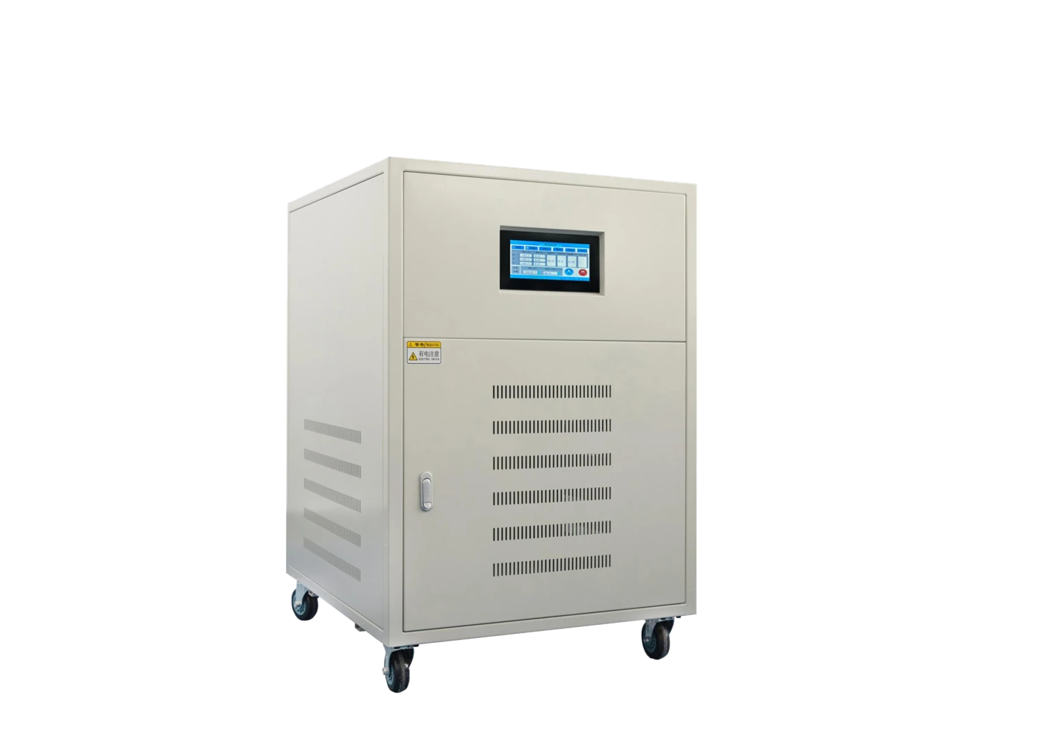
Identify what the supply needs to change
We start by separating the incoming supply from the equipment requirement. Record voltage with its line-to-line or line-to-neutral reference, frequency, phase and conductors on both sides. Then identify whether the difficulty is a fixed voltage mismatch, changing voltage, a frequency mismatch or the speed of one motor. These are different engineering tasks even when a product description uses the general term power converter.
| Task | Equipment function | Main selection question |
|---|---|---|
| Match one nominal AC voltage to another | Transformer with a selected winding ratio | Does the equipment accept the source frequency, and is winding isolation needed? |
| Keep output voltage within an agreed band as input varies | Voltage stabilizer | What input range, load cycle and output behavior must it accommodate? |
| Supply equipment at a specified AC voltage and frequency | Frequency-converting AC power source | What output points, waveform and load behavior must the source support? |
| Control the speed or torque of a compatible motor | Motor drive | What motor, mechanical load and operating sequence must the drive control? |
We use this comparison to establish the required function before discussing capacity, enclosure size or price. Combining functions may be appropriate, but each unit still needs a defined role in the power path.
What a voltage stabilizer changes
We discuss voltage stabilization when the available AC voltage varies and the connected equipment needs a more consistent supply. The required input range, output target, regulation behavior and response to load changes form the selection brief. An input range describes where the equipment can perform its specified function; it does not mean unlimited correction during every disturbance.
Voltage regulation and frequency are separate
A conventional AC voltage stabilizer retains the supply frequency. It also needs incoming energy to power the load: regulation alone does not provide battery ride-through during an outage. We keep frequency conversion, energy storage and isolation as separate requirements when the application needs them.
Our ZFSBW compensated stabilizers and ZFLS oil-immersed stabilizers provide different construction and model-range discussions. Compensation describes a voltage-regulation function; oil immersion describes part of the construction and thermal arrangement. Neither label alone defines the switching method, dynamic response or every feature of the selected configuration.
What a frequency-converting AC source changes
We consider an AC frequency power source when the required output frequency differs from the site supply or a test program calls for several output conditions. Input and output voltage, phase and frequency remain separate fields. We also establish the output current at each operating point, waveform requirements, load power factor and the sequence in which conditions change.
An illustrative test-station brief
Consider a hypothetical station supplied by 230 V single-phase, 50 Hz power that must operate a test article at 230 V single-phase at both 50 Hz and 60 Hz. The voltage is unchanged, yet the frequency requirement already distinguishes this task from voltage stabilization. If the program adds low- and high-voltage points, we record current and test duration at each point instead of selecting only from a nominal kVA value.
Our ZFDP single-phase and ZFSP three-phase AC power-source pages provide the model-range starting points. We discuss isolation, returned energy and interruption support explicitly where required; a frequency-converter label alone does not establish those capabilities.
Where a transformer fits an imported-machine project
We use a transformer to match voltage when the winding arrangement and incoming frequency suit the machine. Separate-winding isolation and shared-winding autotransformer designs provide different relationships between source and load. Our transformer comparison develops that choice; the cases below show why frequency must be considered first.
| Case | Available site supply | Machine requirement | Function to investigate |
|---|---|---|---|
| Voltage differs; frequency matches | 480 V line-to-line, three-phase, 60 Hz | 380 V line-to-line, three-phase, 60 Hz | Voltage transformation, with the winding arrangement and full machine duty defined |
| Voltage and frequency both differ | 480 V line-to-line, three-phase, 60 Hz | 380 V line-to-line, three-phase, 50 Hz only | An equipment-compatible AC conversion arrangement that addresses both requirements |
In the second example, transforming 480 V to 380 V leaves the output at 60 Hz. We therefore review the entire machine input, including motors, controls, heaters and auxiliaries, before defining the supply arrangement. A familiar voltage pair does not settle neutral requirements or frequency compatibility.
Why a motor drive is a separate choice
We distinguish supplying a complete machine from controlling an individual motor. A variable-frequency motor drive operates with the specified motor and mechanical duty, often using a switched output waveform. The machine may also contain control transformers, contactors, heaters and electronic supplies that do not share that motor-output interface.
Placing every machine load on a generic motor-drive output can therefore create an incompatible supply arrangement even if its displayed voltage and frequency appear correct. We discuss motor drives within the motor-control cabinet configuration, while equipment AC sources are considered against the complete electrical load they must supply.
Acceleration, repeated starts, braking and a load that can return energy all affect the motor-side conversation. These details also determine how the upstream supply and protection need to interact with the selected drive.
Continuous, starting and nonlinear loads need separate entries
We ask for the operating cycle alongside the rating. Continuous current sets one demand, while transformer energization, motor starting or charging input capacitors can create a different short-duration demand. Electronic loads may draw current in peaks rather than following a sinusoidal waveform. Their RMS current, peak current and true power factor provide different information.
For a mixed-load machine, we organize controls that remain on continuously, process loads that cycle, and loads that start together. The highest running power may occur at a different moment from the largest startup event. A short load schedule helps us discuss those events without turning an assumed percentage allowance into the complete sizing method.
If a drive or test article can feed energy back toward the source, we record when and for how long that occurs. The conversion arrangement must be suited to that behavior; increasing its nominal output rating does not by itself provide regenerative capability.
Bypass and protection must fit the alternate power path
We treat a bypass as another defined connection between the source and load. If it routes the original site supply around conversion equipment, the load may see the original voltage, frequency and available fault conditions. In our 480 V, 60 Hz to 380 V, 50 Hz example, a direct bypass would not preserve the required output conditions.
We therefore discuss the permitted supply states, load compatibility, interlocks and protection together with your electrical team. A maintenance path, an alternate source and uninterrupted transfer are different design objectives. Their feasibility depends on the complete selected arrangement and operating instructions.
Incoming protection, conductor interfaces and downstream devices also need to suit the resulting circuit conditions. We keep the power diagram and device schedule aligned so the installation team can work from one configuration.
Cooling and installation conditions affect usable performance
We connect capacity selection to the intended ambient conditions, ventilation and operating duty. Heat generated within the equipment must reach the surroundings through the selected cooling arrangement. Dust, moisture, altitude, nearby heat sources and restricted air paths can change the installation requirements or available operating capability.
A larger cabinet footprint may provide access while still leaving an unsuitable airflow path. We consider inlet and outlet clearances, cable approach, door movement and space to remove serviceable components. For an oil-immersed arrangement, fluid-related construction and installation requirements also belong in the equipment brief.
We use the selected configuration's performance information and drawings to develop those details. A general product-family description cannot substitute for the actual operating conditions of the equipment order.
Plan the supply around your application
We can begin with two clear descriptions: the site supply and the machine or test load. Include voltage references, frequency, phase, required neutral, normal current or kVA and the operating sequence. Mention known startup events, output test points, returned energy or interruption requirements.
We then connect the required function to the relevant product range, protection interfaces and installation layout. Our industrial-machine power interface guide explains how the supply, transformer and downstream cabinet information fit together. Your first inquiry can use the available nameplate and process information; detailed drawings can follow as the configuration develops.